Ford Mustang (1999-2004) Service Manual: Column
Removal and Installation
All vehicles
1. Disconnect the battery ground cable and wait at least one minute to allow the depletion of the restraint system backup power supply.
2. WARNING: To avoid the risk of serious personal injury, follow all warnings, cautions, notes and instructions at the beginning of the deactivation procedure.
Deactivate the supplemental restraint system (SRS). For additional information, refer to Supplemental Restraint System (SRS) Deactivation and Reactivation in this section.
3. WARNING: To reduce the risk of serious personal injury, follow all warnings, cautions, notes and instructions in the clockspring removal and installation procedure.
Remove the clockspring (14A664).
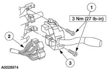
4. Remove the multi-function switch (13K359).
1. Remove the screws.
2. Disconnect the electrical connector.
3. Remove the multi-function switch.
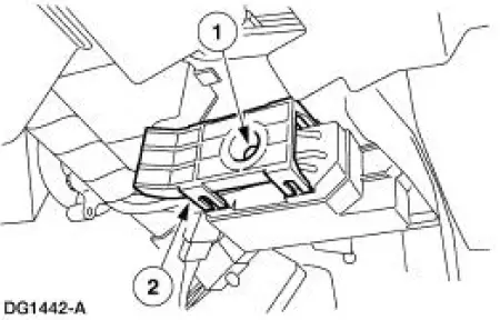
5. Disconnect the ignition switch electrical connector.
1. Remove the bolt.
2. Disconnect the electrical connector.
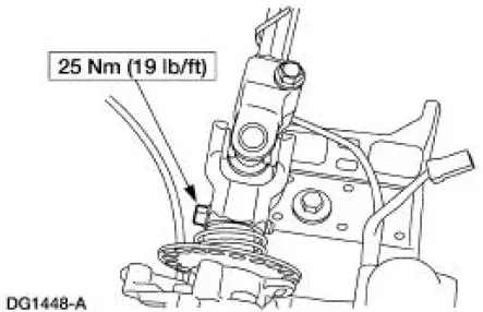
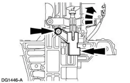
6. Remove the pinch bolt and disconnect the coupling from the steering column.
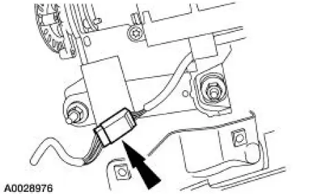
7. Disconnect the electrical connector.
Vehicles with manual transmission
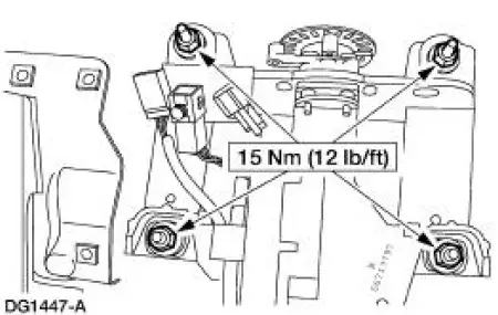
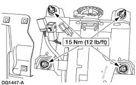
8. Remove the nuts and the steering column.
- Discard the nuts.
Vehicles with automatic transmission
9. Remove the nuts and lower the steering column.
- Discard the nuts.
10. Disconnect the ignition/shifter interlock and remove the steering column.
All vehicles
11. To install, reverse the removal procedure.
12. WARNING: To avoid the risk of serious personal injury, follow all warnings, cautions, notes and instructions at the beginning of the reactivation procedure.
Reactivate the supplemental restraint system (SRS). For additional information, refer to Supplemental Restraint System (SRS) Deactivation and Reactivation in this section.
 Wheel
Wheel
Removal and Installation
1. Disconnect the battery ground cable (14301) and wait at least one minute
to allow the depletion
of the restraint system backup power supply.
2. Turn the steering wheel ...
 Steering Column Shaft
Removal and Installation
1. CAUTION: Do not allow the steering column shaft to rotate while
intermediate shaft
is disconnected or damage to the clockspring can result. If there is evidence
that the
...
Other materials:
Transmission Electronic Control System
The powertrain control module (PCM) and its input/output network
control the following transmission
operations:
Shift timing
Line pressure (shift feel)
Torque converter clutch
The transmission control is separate from the engine control s ...
Crankshaft Runout
Special Tool(s)
Dial Indicator Gauge with
Holding Fixture
100-002 (TOOL-4201-C) or
equivalent
1. NOTE: Crankshaft main bearing journals must be within
specifications before checking runout.
Use the Dial Indicator Gauge with Holding Fixtur ...
Trim Panel - Quarter, Convertible
Special Tool(s)
Safety Belt Bolt Bit
501-010 (T77L-2100-A)
Removal and Installation
1. Lower the convertible top to the full down position.
2. Remove the rear seat cushion.
3. Remove the two bolts and the rear seat backrest.
4. Remove ...
