Ford Mustang (1999-2004) Service Manual: Component Tests
Ball Joint Inspection
1. Raise and support the vehicle.
2. Prior to performing any inspection of the ball joints, inspect the wheel bearings.
3. Position a safety stand beneath the front suspension lower arm (3079) to be tested.
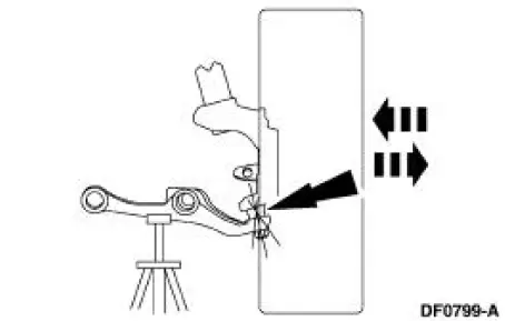
4. While an assistant pulls and pushes the bottom of the tire, observe the relative movement between the lower spindle arm and the front suspension lower arm ball joint. Any movement at or exceeding the specification indicates a worn or damaged lower ball joint. Install a new front suspension lower arm.
Wheel Bearing Inspection
1. Raise the vehicle until the tire is off the floor.
2. NOTE: Make sure the wheel rotates freely and the brake pads are retracted sufficiently to allow movement of the tire and wheel assembly.
Grasp each tire at the top and bottom and move the wheel inward and outward while lifting the weight of the tire off the wheel bearing.
3. If the tire and wheel (hub) is loose on the wheel spindle or does not rotate freely, install a new front wheel hub (1104) as necessary.
 Symptom Chart
Condition
Possible Sources
Action
Dogtracking
Excessive rear
thrust angle.
Front or rear
suspension
components.
Drive axle
damaged.
...
 Camber and Caster Adjustment - Front
All vehicles
1. Remove the rivet. Loosen the nuts and bolt.
Vehicles requiring camber adjustment
2. Move the front suspension camber adjusting plate (3B391) to the required
camber setting.
Vehicl ...
Other materials:
Water Pump - 3.8L
Material
Item
Specification
Motorcraft Premium Gold
Engine Coolant
VC-7-A (in Oregon VC-7-B)
(yellow color)
WSS-M97B51-
A1
Removal and Installation
1. Drain the engine coolant. For additional information, refer to Cooling
System Dra ...
Vehicle certification label
The National Highway Traffic Safety
Administration Regulations require
that a Safety Compliance Certification
Label be affixed to a vehicle and
prescribe where the Safety Compliance
Certification Label may be located.
The Safety Compliance Certification
Labe ...
Cable - Antenna Lead In
Removal
1. Remove the audio unit. Refer to Section.
2. Lower the glove compartment by releasing the stops from the
instrument panel.
3. Disconnect the antenna in-line connector.
4. Remove the antenna lead in cable.
1. Disconnect the pin-type ...
