Ford Mustang (1999-2004) Service Manual: Removal
CAUTION: Since the engine is not free-wheeling, timing procedures must be followed exactly or piston and valve damage can occur.
1. Remove the engine front cover. For additional information, refer to Engine Front Cover in this section.
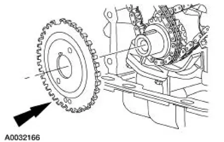
2. Remove the crankshaft sensor ring from the crankshaft.
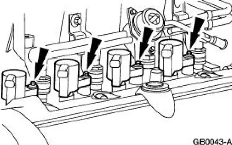
3. Disconnect the eight ignition coil electrical connectors.
4. Remove the bolts and the eight ignition coils.
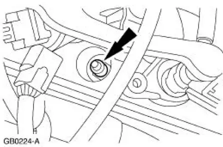
5. NOTE: Use compressed air to remove any foreign material from the spark plug wells before removing the spark plugs.
Remove the spark plugs.
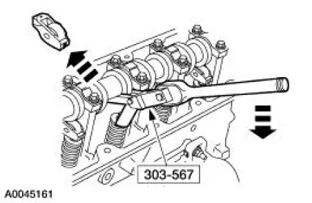
6. NOTE: Rotate the camshaft to the base circle of the camshaft lobe before removing the followers. Keep the roller followers in order when removing.
Using the special tool, remove the 16 roller followers.
- Rotate the crankshaft and camshaft as necessary.
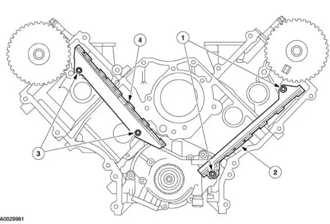
7. Remove the bolts and the LH timing chain tensioner.
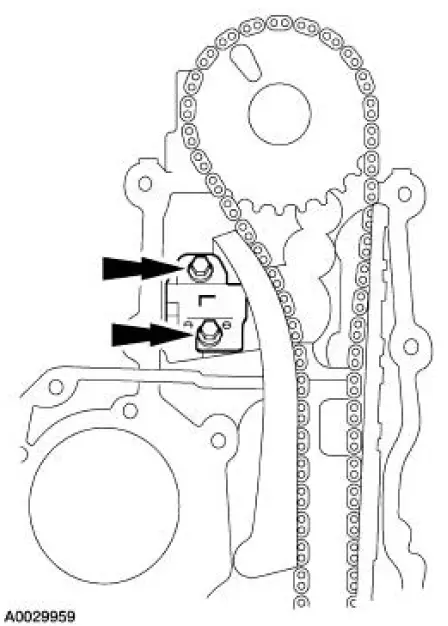
8. Remove the bolts and the RH timing chain tensioner.
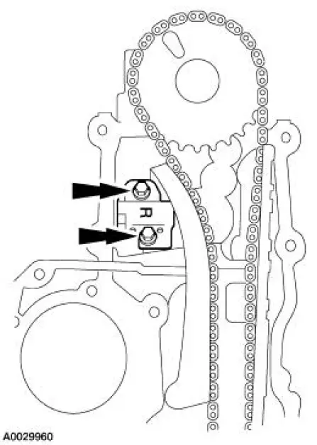
9. Remove the LH and the RH timing chain tensioner arm from the dowel pins.
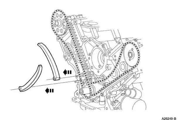
10. Remove the timing chains and the crankshaft sprocket.
11. Remove the timing chain guides.
1. Remove the bolts.
2. Remove the LH timing chain guide.
3. Remove the bolts.
4. Remove the RH timing chain guide.
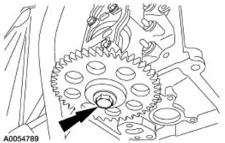
12. NOTE: RH shown, LH similar.
Install the special tool.
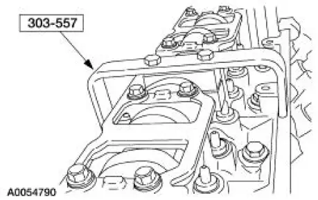
13. NOTE: RH shown, LH similar.
Remove the bolt and the camshaft gear.
 Timing Drive Components
Special Tool(s)
Compressor, Valve Spring
303-567 (T97P-6565-AH)
Holding Tool, Crankshaft
303-448 (T93P-6303-A)
Aligner, Camshaft Position
303-557 (T96T-6256-B) ...
 Installation
1. CAUTION: The timing chain procedures must be followed exactly or
damage to the
valve and pistons will result.
Compress the tensioner plunger, using an edge of a vise.
2. While holding the ratch ...
Other materials:
A/C Compressor Pressure Relief Valve
An A/C compressor pressure relief valve is incorporated into the compressor
A/C manifold and tube to:
relieve unusually high refrigerant system discharge pressure buildups.
For specifications
regarding operating pressure(s), refer to Section.
prevent ...
Inspection and Verification
1. The interior lighting system is a generic electronic module (GEM)
controlled system.
2. Verify the customer concern by operating the interior lighting system.
3. Visually inspect for the following obvious signs of mechanical and
electrical damage.
...
Stability Control
PRINCIPLES OF OPERATION
WARNING: Vehicle modifications involving braking system,
aftermarket roof racks, suspension, steering system, tire
construction and wheel or tire size may change the handling
characteristics of your vehicle and may adversely affect the ...
