Ford Mustang (1999-2004) Service Manual: Removal
WARNING: Do not smoke or carry lighted tobacco or open flame of any type when working on or near any fuel related components. Highly flammable mixtures are always present and may be ignited. Failure to follow these instructions may result in personal injury.
1. Disconnect the battery ground cable (14301). For additional information, refer to Section.
2. Disconnect the air cleaner outlet tube. For additional information, refer to Section.
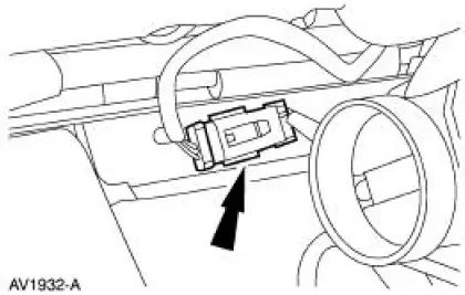
3. Disconnect the 42 pin connector.
4. Separate the wiring harness retainers from the dash panel.
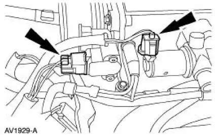
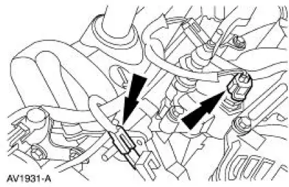
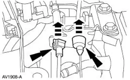
5. Disconnect the following connectors:
- Throttle position (TP) sensor
- Idle air control (IAC) valve
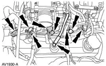
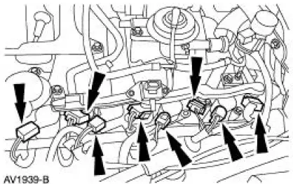
6. Disconnect the following connections:
- Four ignition coils
- Four fuel injectors
- Positive crankcase ventilation (PCV) hose from valve cover.
7. Disconnect the following connectors:
- RH radio ignition interference capacitor
- Engine coolant temperature (ECT) sensor
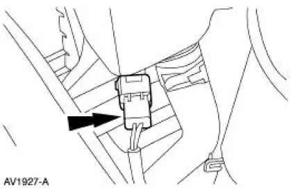
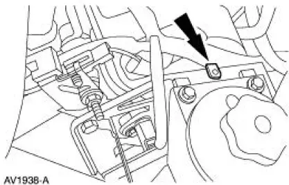
8. Disconnect the 16 pin connector
9. Raise the vehicle. For additional information, refer to Section.
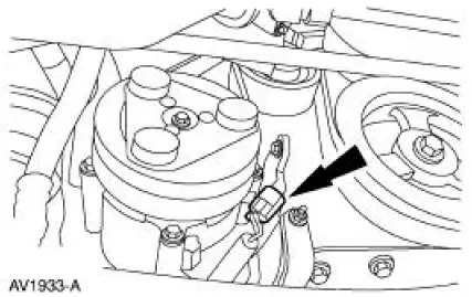
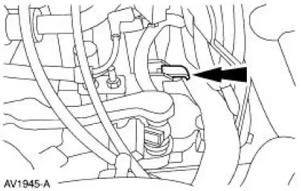
10. Disconnect the crankshaft position (CKP) sensor electrical connector.
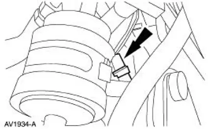
11. Disconnect the A/C compressor clutch electrical connector.
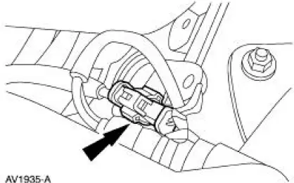
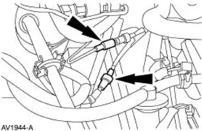
12. Disconnect the RH heated oxygen sensor (HO2S) electrical connector.
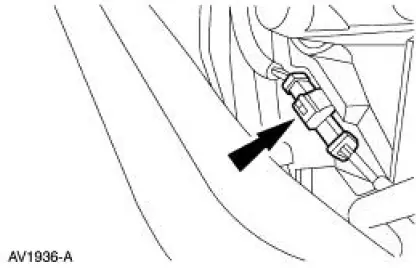
13. Disconnect the LH heated oxygen sensor (HO2S) electrical connector.
14. Lower the vehicle.
15. Disconnect the coolant reservoir electrical connector.
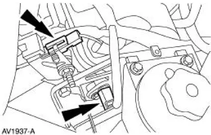
16. Disconnect the following connectors:
- Camshaft position (CMP) sensor
- LH radio ignition interference capacitor
17. Separate the wiring harness from the power steering reservoir bracket.
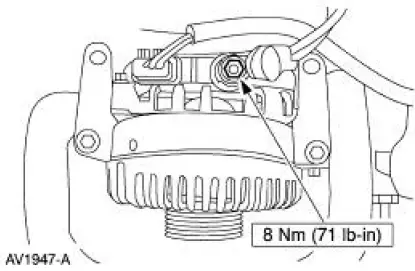
18. Disconnect the generator connectors:
- Battery power supply wire
- Voltage regulator
19. Disconnect the following connectors:
- LH fuel injectors
- LH ignition coils
20. Disconnect the following connectors:
- Exhaust vacuum regulator (EVR)
- Ground wire
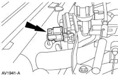
21. Disconnect the EGR pressure transducer electrical connector.
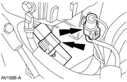
22. Disconnect the fuel pressure sensor electrical connector and the vacuum hose.
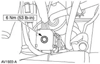
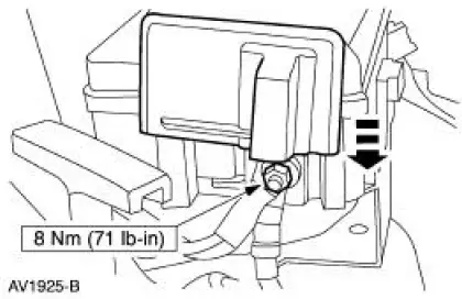
23. Slide cover up and remove the nut and the power distribution box battery supply wire.
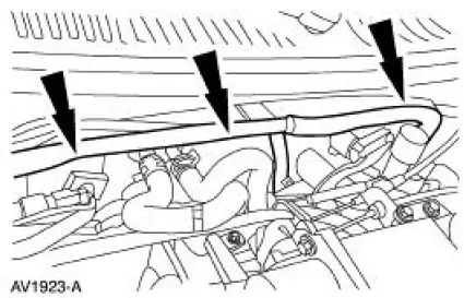
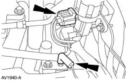
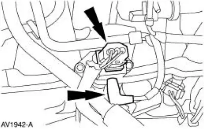
24. NOTE: These two connectors are located under the power distribution box.
Disconnect the two connectors.
25. Disconnect the main vacuum hose.

26. Disconnect the vacuum lines
27. Squeeze the two locking tabs, and remove the accelerator cable and the speed control cable (if equipped) from the bracket and position aside.
28. Separate the fuel charging wiring (9D930) from the rear of the intake manifold (9424) and remove from the vehicle.

 Installation
1. Position the fuel charging wiring in the vehicle and attach to the rear of
the intake manifold.
2. NOTE: Make sure the locking clips are fully engaged into the bracket.
Reposition the accel ...
Other materials:
Safety Precautions
WARNING: Never run the engine with one wheel off the ground, for
example, when
changing a tire. The wheel(s) resting on the ground could cause the vehicle to
move.
WARNING: The tire and wheel must always be correctly matched. It is very
important to
determ ...
Engine Ignition (Description and Operation)
The ignition coil (12029), which is mounted on the upper intake manifold, can
be described as a coil
pack containing three separate coil units. Each coil unit is individually
controlled by the powertrain
control module (PCM) (12A650) through separate wire le ...
Inspection and Verification
WARNING: Never remove the pressure relief cap while the engine is
operating or when the
cooling system is hot. Failure to follow these instructions can result in damage
to the cooling
system or engine or personal injury. To avoid having scalding hot coolant ...
