Ford Mustang (1999-2004) Service Manual: Axle Housing
Removal and Installation
1. CAUTION: The vehicle must be on level ground and at curb height.
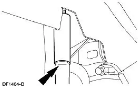
Mark the rear shock absorbers relative to their protective sleeve.
- During installation, raise the suspension to this reference mark before tightening the suspension fasteners.
2. Raise and support the vehicle.
3. Remove the rear wheel and tire assemblies.
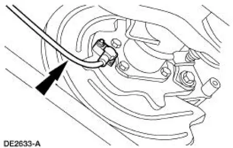
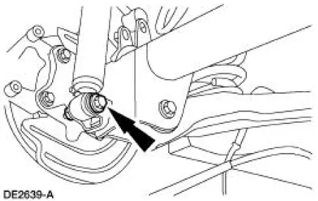
4. NOTE: If necessary, use Rust Penetrant and Inhibitor F2AZ-19A501-A meeting Ford specification ESR-M99C56-A to loosen the sensor for removal.
Remove the rear anti-lock brake sensors from the rear disc brake adapters
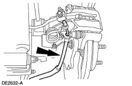
5. Disconnect the parking brake cables and conduits from the rear disc brake calipers.
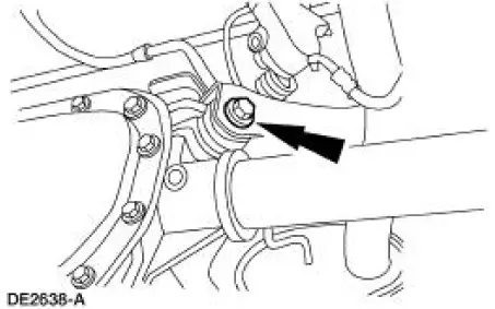
6. Disconnect the rear axle drive line vibration damper from the axle.

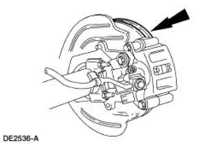
7. CAUTION: Index-mark the brake discs and the wheel studs prior to brake disc removal.
CAUTION: Do not allow the calipers to hang from the brake hoses.
Remove the rear brake discs.
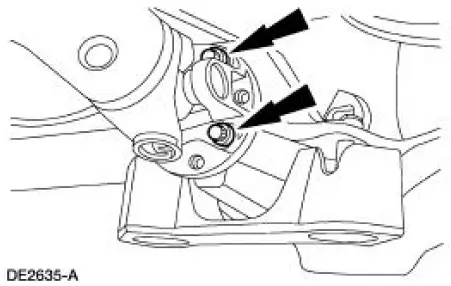
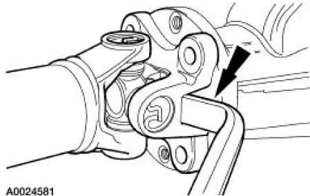
8. CAUTION: Index-mark the driveshaft flange and pinion flange (4851) to maintain initial balance during installation.
CAUTION: The driveshaft centering socket yoke fits tightly on the pinion flange pilot. Never hammer on the driveshaft or any of its components to disconnect the yoke from the flange. Pry only in the area shown, with a suitable tool, to disconnect the yoke from the flange.
Disconnect and position the driveshaft out of the way.
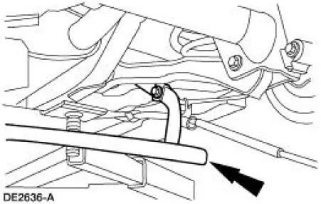
9. Remove the stabilizer bar.
10. Position a suitable transmission jack under the differential housing (4010) for support and strap it securely in place.
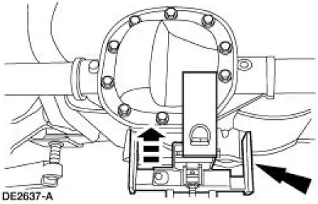
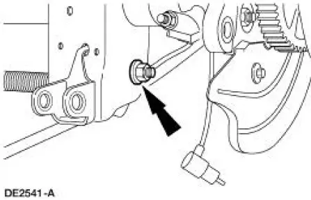
11. Remove and discard the nuts and bolts retaining the upper suspension arm and bushings to the differential housing.
12. Remove and discard the nuts and bolts retaining the shock absorbers to the axle.
13. Lower the differential housing to unload the rear springs.
14. Remove the rear springs.
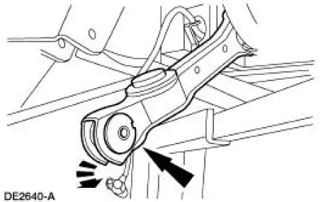
15. Remove and discard the nuts and bolts retaining the lower suspension arm and bushings to the axle.
16. Disconnect the lower suspension arm and bushings from the axle.
17. Remove the axle from the vehicle.
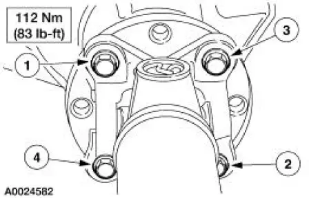
18. CAUTION: Align the index marks on the driveshaft centering socket yoke and the pinion flange.
CAUTION: Install the driveshaft with new bolts. If new bolts are not available, apply Threadlock and Sealer EOAZ-19554-AA or equivalent meeting Ford specification WSKM2G351- A5 to the threads of the original bolts.
CAUTION: The driveshaft centering socket yoke fits tightly on the pinion flange pilot. To make sure that the yoke seats squarely on the flange, tighten the bolts evenly in a cross pattern as shown.
CAUTION: Raise the suspension to the reference marks on the rear shock absorbers before tightening the suspension fasteners.
NOTE: Apply High Temperature Nickel Anti-Sieze Lubricant F6AZ-9L494-AA meeting Ford specification ESE-M124A-A to the rear anti-lock brake sensor body where it will make contact when installed.
Follow the removal procedure in reverse order.
- Refer to Section for rear suspension fastener tightening specifications.
- Refer to Section for wheel nut tightening specification.
 Installation
All axles
1. Position the ring gear and the differential case. Align the bolt holes by
starting two bolts through
the holes in the differential case and the ring gear. Press the ring gear on the
dif ...
 Differential Case and Ring Gear - Conventional
Special Tool(s)
2-Jaw Puller
205-D072 (D97L-4221-A) or
equivalent
Installer, Differential Side
Bearing
205-010 (T57L-4221-A2)
Step Plate
205-D061 (D83T-4205-C2) or
...
Other materials:
Supercharger Belt
Removal and Installation
1. Remove the supercharger drive belt cover.
2. Rotate the supercharger belt tensioner clockwise and remove the
supercharger belt.
3. To install, reverse the removal procedure. ...
Air Cleaner - 4.6L (2V) and 4.6L (4V)
Removal and Installation
Mach I
1. Disconnect the air intake scoop outlet tube.
All vehicles
2. Remove the air cleaner outlet tube from the throttle body. For
additional information, refer to Air
Cleaner Outlet Pipe-4.6L (2V) or Air Cleaner Outlet Pipe- ...
Electronic Vibration Analyzer (EVA)
The EVA is a hand-held electronic diagnostic tool which will assist in
locating the source of
unacceptable vibrations. The vibration sensor can be remotely mounted anywhere
in the vehicle for
testing purposes. The unit displays the three most common vibratio ...
