Ford Mustang (1999-2004) Service Manual: Brake Booster - Vacuum (Description and Operation)
Power Brake Booster
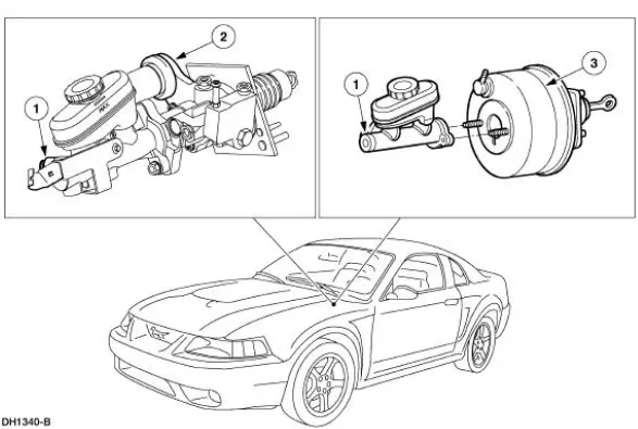
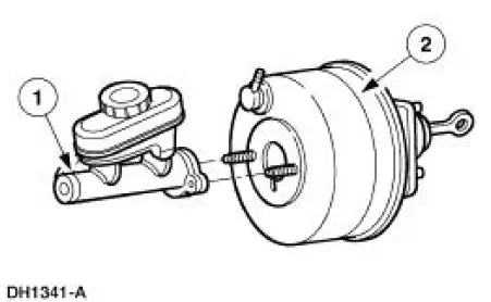
The vacuum type power brake booster (2005):
- is a dual diaphragm, vacuum assisted power brake booster
- reduces brake pedal force and travel distance.
- is located on the LH side of the bulkhead in the engine compartment, between the brake pedal (2455) and the brake master cylinder (2140).
- is divided into separate chambers by the diaphragms.
- will not operate if vacuum is restricted or if any of the vacuum related power brake components fail.
- is installed as an assembly.
If the power assist fails, the brake system will continue to operate with increased brake pedal effort.
Hose and Check Valve
The power brake booster check valve (2365):
- is located on the front of the power brake booster.
- is installed separately; (install a new grommet when installing a new check valve).
- is positioned between the power brake booster and the power brake booster hose.
- closes when the engine is turned off.
- in the closed position, traps engine vacuum in the power brake booster
- retains vacuum to provide several power assisted brake applications with the engine off.

 Power Brake Actuation
Torque Specifications
...
 Brake Booster - Hydro-Boost (Description and Operation)
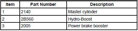
The Hydro-Boost brake booster is a hydraulically operated brake booster
powered by the power
steering pump (3A674). The power steering pump provides the fluid pressure to
operate both the
power brak ...
Other materials:
Suction Accumulator
NOTE: Installation of a new suction accumulator is not required when
repairing the air conditioning
system except when there is physical evidence of contamination from a failed A/C
compressor or
damage to the suction accumulator.
In addition to th ...
Pinpoint Tests
CAUTION: Do not make jumper connections except as directed.
Incorrect connections
may damage the voltage regulator test terminals, fuses, or fuse links.
CAUTION: Do not allow any metal object to come in contact with the
generator housing
and inter ...
Diagnostic Strategy
Troubleshooting an electronically controlled automatic transmission
is simplified by using the proven
method of diagnosis. One of the most important things to remember is
that there is a definite
procedure to follow.
NOTE: Do not take any short cut ...
