Ford Mustang (1999-2004) Service Manual: Caliper (Disassembly and Assembly)
Special Tool(s)
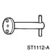 |
Rear Caliper Piston Adjuster 206-026 (T87P-2588-A) |
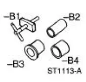 |
Rear Caliper Spring Compressor Set 206-S027 (T87P-2588-B) |
Disassembly
1. Remove the rear disc brake caliper (2552). For additional information, refer to Caliper in the Removal and Installation portion of this section.
2. Drain the brake fluid from the rear disc brake caliper.
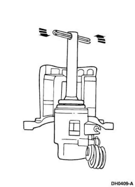
3. Secure the rear disc brake caliper in a vise.
4. Turn the rear disc brake piston and adjuster (2B588) counterclockwise with Rear Caliper Piston Adjuster.
5. Remove the rear disc brake piston and adjuster from the caliper bore.
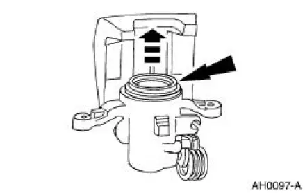
6. Remove and discard the piston dust boot seal and piston seal from the caliper bore.
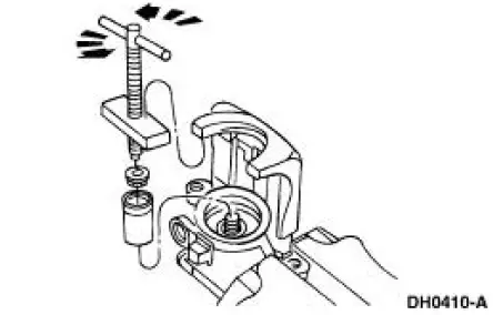
7. CAUTION: The parking brake lever pin retainer clip (2A746) and spring cover are spring-loaded. Use care when removing the parking brake lever pin retainer clip.
Remove the parking brake lever pin retainer clip.
- Unload the spring tension from the parking brake lever pin retainer clip and spring cover using Screw and Cross Block, a 6-mm washer head nut and a 1/2-inch drive 14-mm socket.
- Remove the parking brake lever pin retainer clip with suitable snap-ring pliers.
- Remove Screw and Cross Block.
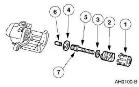
8. Remove the following components:
1. spring cover
2. spring
3. washer
4. key plate
5. push rod
6. strut pin
7. push rod O-ring
9. Remove and discard the O-ring seal from the push rod.
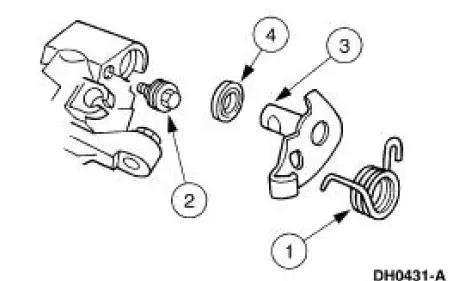
10. Remove the parking brake lever (2A637).
1. Remove the parking brake return spring (2456).
2. Remove the limiting bolt (2A795).
3. Remove the parking brake lever.
4. Remove the parking brake lever shaft seal from the caliper bore.
Assembly
1. CAUTION: Do not reuse piston seals or dust boots. Install new seals or dust boots or damage to the vehicle can occur.
NOTE: Use new brake fluid when assembling and bleeding the brake system.
NOTE: Lightly lubricate the parking brake lever bore, limiting bolt, parking brake lever shaft and parking brake shaft recess with Silicone Dielectric Compound D7AZ-19A331-A or equivalent meeting Ford specification ESE-M1C171-A.
Follow the disassembly procedure in reverse order.
 Shield
Removal
1. Remove the brake disc (2C026). For additional information, refer
to Disc in this section.
2. Remove the brake disc shield bolts.
Installation
1. Follow the removal procedure in r ...
 Parking Brake and Actuation
Torque Specifications
...
Other materials:
Wheel Hub - Cobra
Special Tool(s)
2-3 Jaw Puller
205-D026 (D80L-1013-A) or
Equivalent
Driver
205-199 (T83T-3132-A1)
Front Hub Remover Replacer
204-069 (T81P-1104-C)
Hub Bearing Remover
204-081 (T83P-1104-AH2)
...
Inspection and Verification
NOTE: Upon installation of a new GEM, the module must be
reconfigured. For additional information,
refer to Section.
1. The warning lamps are a GEM controlled system; refer to Section.
2. Verify the customer concern by operating the system in questio ...
Cleaning
1. Fabricate a cleaning tool from a 1/8 inch diameter brazing rod.
2. Cut an abrasive pad from maroon colored 3M Scotch Brite with the
dimensions corresponding
to the coupling size.
3. Assemble the pad to the tool.
4. Coat the abrasive pad with PAG Refri ...
