
Ford Mustang (1999-2004) Service Manual: Cleaning
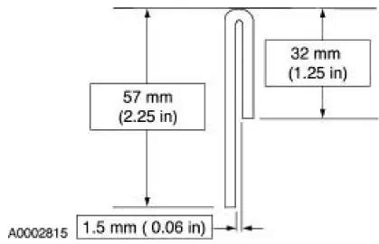
1. Fabricate a cleaning tool from a 1/8 inch diameter brazing rod.
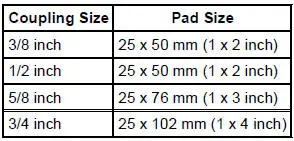
2. Cut an abrasive pad from maroon colored 3M Scotch Brite with the dimensions corresponding to the coupling size.
3. Assemble the pad to the tool.
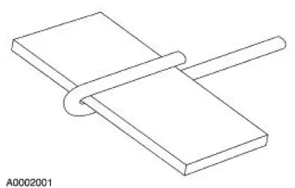
4. Coat the abrasive pad with PAG Refrigerant Compressor Oil (R-134a Systems) or equivalent.
5. Roll the pad on the tool and install it in a variable speed drill motor.
6. CAUTION: Maintain low speed drill rotation when inserting or removing the cleaning tool to prevent axial scratches which may cause future leaks.
Polish for one minute at moderate speed (less than 1,500 rpm) or until the surface is clean and free of scratches or foreign material.
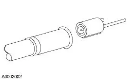
7. Clean the fitting with a lint-free cloth.
8. Inspect the surface for grooves or scratches. If grooves and scratches are still present, install a new component.
9. Clean the O-ring seal grooves with a 300 mm (12 inch) length of natural fiber string.
- Loop the string around the grooves and pull the string back and forth.
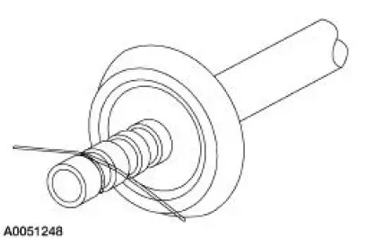
10. Remove any foreign material from the grooves with a lint-free cloth.
 Disconnect
1. Remove the A/C tube lock coupling clip (19E746), if equipped.
2. Fit the special tool to the spring lock coupling.
3. Push the tool into the cage opening to release the female fitting from the ...
 Connect
1. Install the A/C tube lock coupling spring.
2. Lubricate the inside of the coupling with PAG Refrigerant Compressor Oil
(R-134a Systems) or
equivalent.
3. CAUTION: Use only the new O-ring seals ...
Other materials:
Installation
1. NOTE: If the valve cover is not secured within four minutes, the sealant
must be removed and
the sealing area cleaned with metal surface cleaner. Allow to dry until there is
no sign of
wetness, or four minutes, whichever is longer. Failure to follow this ...
Differential Case and Ring Gear - Traction-Lok
Special Tool(s)
2-Jaw Puller
205-D072 (D97L-4221-A) or
equivalent
Gauge, Differential Clutch
205-022 (T66L-4204-A)
Gauge, Differential Clutch
205-135 (T80P-4946-A)
Installer, Differential Side
Bearing
205-010 (T57 ...
Push Rods - Inspection
1. CAUTION: Do not attempt to straighten push rods.
Check the ends of the push rods for nicks, grooves, roughness or
excessive wear. Install new
push rods as necessary. Refer to the appropriate section in Group 303 for
the procedure.
The push rods ca ...
