Ford Mustang (1999-2004) Service Manual: Catalyst Monitor Sensor
Special Tool(s)
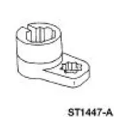 |
Socket, Exhaust Gas Oxygen Sensor 303-476 (T94P-9472-A) |
Material
| Item | Specification |
| Penetrating and Lock Lubricant or equivalent | E8AZ-19A501- B |
Removal and Installation
1. Disconnect the battery ground cable. For additional information, refer to Section.
2. Raise and support the vehicle. For additional information, refer to Section.
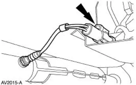
3. NOTE: Two catalyst monitor sensors are used for the engine control system. They are located in the dual converter Y pipe downstream from the catalyst. The left side catalyst monitor sensor is shown, the right side is similar.
Disconnect the connector.
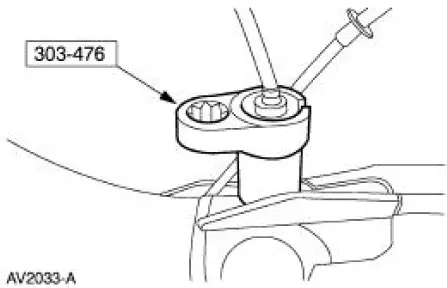
4. NOTE: If necessary, lubricate the sensors with penetrating and lock lubricant to assist in removal.
Using the special tool, remove the catalyst monitor sensors from the dual converter Y pipe.
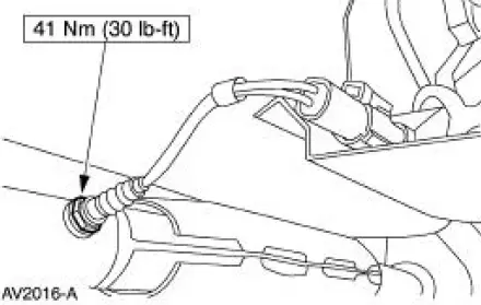
5. To install, reverse the removal procedure.
 Heated Oxygen Sensor (HO2S)
Special Tool(s)
Socket, Exhaust Gas Oxygen
Sensor
303-476 (T94P-9472-A)
Material
Item
Specification
Penetrating and Lock Lubricant
or equivalent
E8AZ-19A501-
B
...
 Clutch Pedal Position (CPP) Switch
Removal
1. Disconnect the battery ground cable. For additional information,
refer to Section.
2. Disconnect the connector.
3. Remove the bolt and the clutch pedal position (CPP) switch.
In ...
Other materials:
Mass Air Flow (MAF) Sensor - 3.8L
Removal
CAUTION: The mass air flow (MAF) sensor hot wire sensing
element and housing are
calibrated as a unit and must be repaired as a complete assembly. Do not
damage the sensing
element (internal to housing) or possible failure to the mass air f ...
Component Tests
Ball Joint Inspection
1. Raise and support the vehicle.
2. Prior to performing any inspection of the ball joints, inspect the wheel
bearings.
3. Position a safety stand beneath the front suspension lower arm (3079) to be
tested.
4. While an assistant pul ...
Accelerator Cable - 4.6L (2V)
Removal and Installation
1. Push the accelerator cable nylon bushing out of the accelerator pedal and
shaft arm.
2. Remove the bolts retaining the accelerator cable to the dash panel.
3. Disconnect the accelerator cable from the throttle body by rotating ...
