Ford Mustang (1999-2004) Service Manual: Electronic Engine Controls
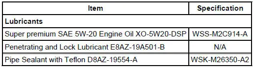
General Specifications
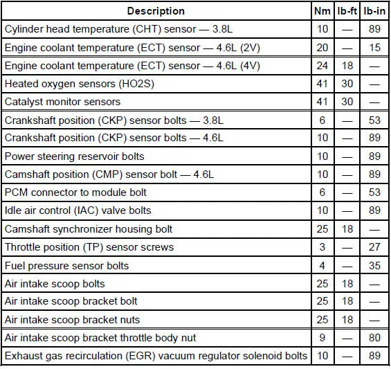
Torque Specifications
- Electronic Engine Controls (Description and Operation)
- Electronic Engine Controls - Cobra
- Temperature and Manifold Absolute Pressure (T-MAP) Sensor - Cobra
- Camshaft Position (CMP) Sensor - 3.8L
- Camshaft Position (CMP) Sensor - 4.6L
- Intake Manifold Runner Control (IMRC) Actuator - 3.8L
- Crankshaft Position (CKP) Sensor - 3.8L
- Crankshaft Position (CKP) Sensor - 4.6L
- Powertrain Control Module (PCM)
- Throttle Position (TP) Sensor
- Idle Air Control (IAC) Valve - 3.8L
- Idle Air Control (IAC) Valve - 4.6L (2V)
- Idle Air Control (IAC) Valve - Cobra
- Idle Air Control (IAC) Valve - Mach I
- Cylinder Head Temperature (CHT) Sensor - 3.8L
- Engine Coolant Temperature (ECT) Sensor - 4.6L (2V)
- Engine Coolant Temperature (ECT) Sensor - Cobra
- Engine Coolant Temperature (ECT) Sensor - Mach I
- Mass Air Flow (MAF) Sensor - 3.8L
- Mass Air Flow (MAF) Sensor - 4.6L (2V)
- Mass Air Flow (MAF) Sensor - Cobra
- Mass Air Flow (MAF) Sensor - Mach I
- Heated Oxygen Sensor (HO2S)
- Catalyst Monitor Sensor
- Clutch Pedal Position (CPP) Switch
- Fuel Pressure Sensor
- Supercharger Bypass Vacuum Solenoid - Actuator
 Evaporative Emission Test Port
Removal and Installation
1. Disconnect the pin-type retainer.
2. Raise and support the vehicle. For additional information, refer to
Section.
3. Remove the RH front wheel. For additional informa ...
 Electronic Engine Controls (Description and Operation)
The electronic engine controls consist of the following:
powertrain control module (PCM)
throttle position (TP) sensor
idle air control (IAC) valve
engine coolant temperature (ECT) sens ...
Other materials:
Disassembly
1. Remove the differential assembly from the differential housing. For
additional information, refer
to Differential Case in this section.
2. Remove the bolts.
3. CAUTION: Do not damage the threads in the bolt holes.
Insert a punch in the bolt holes and d ...
Thermostat - 3.8L
Material
Item
Specification
Gasket Adhesive
TA-6 or equivalent
WSS-M2G408-
A
Motorcraft Premium Gold
Engine Coolant
VC-7-A (in Oregon VC-7-B)
(yellow color)
WSS-M97B51-
A1
Removal and Installation
1. Drain the engine cool ...
Component Tests
Engine Oil Leaks
NOTE: When diagnosing engine oil leaks, the source and location of
the leak must be positively
identified prior to repair.
Prior to carrying out this procedure, clean all sealing surface areas with a
suitable solvent to remove all
tra ...
