Ford Mustang (1999-2004) Service Manual: Component Tests
Ball Joint Inspection
1. Raise and support the vehicle.
2. Prior to performing any inspection of the ball joints, inspect the wheel bearings.
3. Position a safety stand beneath the front suspension lower arm (3079) to be tested.
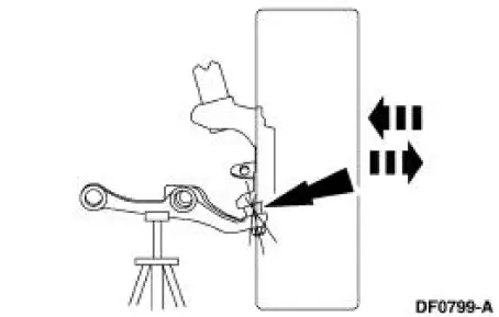
4. While an assistant pulls and pushes the bottom of the tire, observe the relative movement between the lower spindle arm and the front suspension lower arm ball joint. Any movement at or exceeding the specification indicates a worn or damaged lower ball joint. Install a new front suspension lower arm.
Wheel Bearing Inspection
1. Raise the vehicle until the tire is off the floor.
2. NOTE: Make sure the wheel rotates freely and the brake pads are retracted sufficiently to allow movement of the tire and wheel assembly.
Grasp each tire at the top and bottom and move the wheel inward and outward while lifting the weight of the tire off the wheel bearing.
3. If the tire and wheel (hub) is loose on the wheel spindle or does not rotate freely, install a new front wheel hub (1104) as necessary.
 Symptom Chart
Condition
Possible Sources
Action
Dogtracking
Excessive rear
thrust angle.
Front or rear
suspension
components.
Drive axle
damaged.
...
 Camber and Caster Adjustment - Front
All vehicles
1. Remove the rivet. Loosen the nuts and bolt.
Vehicles requiring camber adjustment
2. Move the front suspension camber adjusting plate (3B391) to the required
camber setting.
Vehicl ...
Other materials:
Battery Cables
Removal
WARNING: Batteries normally produce explosive gases which can
cause personal injury.
Therefore, do not allow flames, sparks or lighted substances to come
near the battery. When
charging or working near a battery, always shield your face an ...
Valve - Seat Inspection
Valve and Seat Refacing Measurements
CAUTION: After grinding valves or valve seats, check valve
clearance.
1. Check the valve head and seat.
Check valve angles.
Check margin width.
Refer to the appropriate section in Group 303 for the procedure.
...
Crash sensors and airbag indicator
WARNING: Modifying or adding equipment to the front end of
your vehicle (including frame, bumper, front end body structure
and tow hooks) may affect the performance of the airbag system,
increasing the risk of injury. Do not modify the front end of your
vehicl ...
