Ford Mustang (1999-2004) Service Manual: Column
Removal and Installation
All vehicles
1. Disconnect the battery ground cable and wait at least one minute to allow the depletion of the restraint system backup power supply.
2. WARNING: To avoid the risk of serious personal injury, follow all warnings, cautions, notes and instructions at the beginning of the deactivation procedure.
Deactivate the supplemental restraint system (SRS). For additional information, refer to Supplemental Restraint System (SRS) Deactivation and Reactivation in this section.
3. WARNING: To reduce the risk of serious personal injury, follow all warnings, cautions, notes and instructions in the clockspring removal and installation procedure.
Remove the clockspring (14A664).
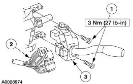
4. Remove the multi-function switch (13K359).
1. Remove the screws.
2. Disconnect the electrical connector.
3. Remove the multi-function switch.
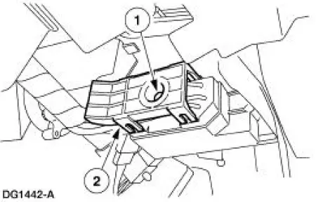
5. Disconnect the ignition switch electrical connector.
1. Remove the bolt.
2. Disconnect the electrical connector.
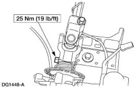
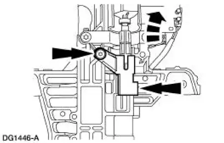
6. Remove the pinch bolt and disconnect the coupling from the steering column.
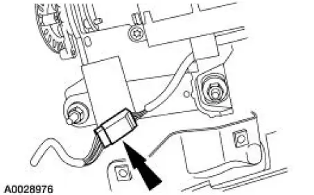
7. Disconnect the electrical connector.
Vehicles with manual transmission
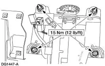
8. Remove the nuts and the steering column.
- Discard the nuts.
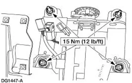
Vehicles with automatic transmission
9. Remove the nuts and lower the steering column.
- Discard the nuts.
10. Disconnect the ignition/shifter interlock and remove the steering column.
All vehicles
11. To install, reverse the removal procedure.
12. WARNING: To avoid the risk of serious personal injury, follow all warnings, cautions, notes and instructions at the beginning of the reactivation procedure.
Reactivate the supplemental restraint system (SRS). For additional information, refer to Supplemental Restraint System (SRS) Deactivation and Reactivation in this section.
 Wheel
Wheel
Removal and Installation
1. Disconnect the battery ground cable (14301) and wait at least one minute
to allow the depletion
of the restraint system backup power supply.
2. Turn the steering wheel ...
 Steering Column Shaft
Removal and Installation
1. CAUTION: Do not allow the steering column shaft to rotate while
intermediate shaft
is disconnected or damage to the clockspring can result. If there is evidence
that the
...
Other materials:
Weld Nut Repair - "J" Nut, Restraints Control
Module
(RCM)
WARNING: To avoid accidental deployment and possible personal
injury, the backup
power supply must be depleted before repairing or replacing any front or
side air bag
supplemental restraint system (SRS) components and before servicing,
replacing, ...
Fuel quality
Note: Use of any fuel other than those recommended may cause
powertrain damage and a loss of vehicle performance; repairs may not be
covered under warranty.
Choosing the Right Fuel
Use only unleaded fuel or unleaded fuel blended with a maximum of
15% ethanol. ...
Suspension System - General Information
Alignment Specifications
General Specifications
Torque Specifications
Description
Nm
lb-ft
Front suspension camber adjustment plate bolt
40
30
Front suspension camber adjustment plate nuts
40
30
Rear camber adjustment nut ...
