
Ford Mustang (1999-2004) Service Manual: Wheel
Removal and Installation
1. Disconnect the battery ground cable (14301) and wait at least one minute to allow the depletion of the restraint system backup power supply.
2. Turn the steering wheel to the straight-ahead position and the ignition switch to the OFF position.
3. WARNING: To avoid the risk of serious personal injury, follow all warnings, cautions, notes and instructions in the beginning of the deactivation procedure.
Deactivate the supplemental restraint system (SRS). For additional information, refer to Supplemental Restraint System (SRS) Deactivation and Reactivation in this section.
4. WARNING: To avoid risk of serious personal injury, follow all warnings, cautions, notes and instructions in the driver air bag removal and installation procedure.
Remove the driver air bag module. 5. Remove and discard the steering wheel retaining bolt.
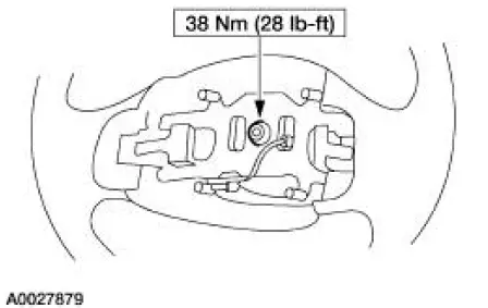
6. CAUTION: Removing the steering wheel without using a puller can damage the column bearings.
Use a suitable puller to remove the steering wheel (3600).
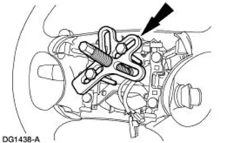
7. Remove the steering wheel while routing the wires from the clockspring through the steering wheel.
8. To install, reverse the removal procedure.
9. WARNING: To avoid the risk of serious personal injury, follow all warnings, cautions, notes and instructions at the beginning of the reactivation procedure.
Reactivate the supplemental restraint system (SRS). For additional information, refer to Supplemental Restraint System (SRS) Deactivation and Reactivation in this section.
 Ignition Switch Lock Cylinder - Non-Functional
Removal and Installation
1. NOTE: Make sure the front wheels are in the straight-ahead
position.
Disconnect the battery ground cable (14301) and wait at least one minute to
allow the depletion
of t ...
 Column
Removal and Installation
All vehicles
1. Disconnect the battery ground cable and wait at least one minute to allow
the depletion of the
restraint system backup power supply.
2. WARNING: To avoid ...
Other materials:
Crash sensors and airbag indicator
WARNING: Modifying or adding equipment to the front end of
your vehicle (including frame, bumper, front end body structure
and tow hooks) may affect the performance of the airbag system,
increasing the risk of injury. Do not modify the front end of your
vehicl ...
Pressure
1. Clean all dirt from and remove the brake master cylinder filler
cap and fill the brake master
cylinder reservoir with the specified brake fluid.
2. NOTE: Master cylinder pressure bleeder adapter tools are available
from various manufacturers
of pres ...
Manual Transmission and Clutch (Diagnosis and Testing)
Inspection and Verification
It is important to get an accurate description of the concern before
any diagnosis can be carried out.
Ask questions as to whether it occurs when hot or cold, during shifting,
driving at a particular speed or
in a parti ...
