Ford Mustang (1999-2004) Service Manual: Compressor to Condenser Discharge Line - 4.6L
Material
| Item | Specification |
| PAG Refrigerant Compressor Oil (R-134a Systems) F7AZ-19589-DA (Motorcraft YN- 12-C) | WSH-M1C231- B |
Removal and Installation
NOTE: Installation of a new suction accumulator is not required when repairing the air conditioning system except when there is physical evidence of contamination from a failed A/C compressor or damage to the suction accumulator.
1. Recover the refrigerant. For additional information, refer to Section.
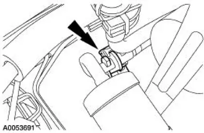
2. Disconnect the dual-function pressure switch electrical connector and remove the switch.
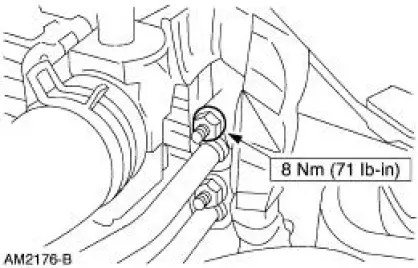
3. Remove the A/C muffler bracket nut.
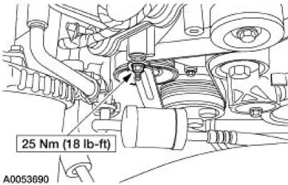
4. Disconnect the fitting at the condenser.
- Discard the O-ring seal.
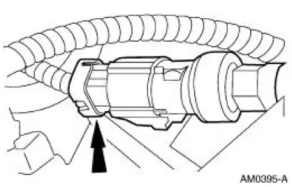
5. Disconnect the spring lock coupling at the compressor manifold and tube.
- Discard the O-ring seals.
6. Remove the compressor to condenser discharge line.
7. To install, reverse the removal procedure.
- Install new O-ring seals lubricated in clean PAG oil. For additional information, refer to Section.
- Lubricate the refrigerant system with the correct amount of clean PAG oil. For additional information, refer to Section.
8. Evacuate, leak test and charge the refrigerant system. For additional information, refer to Section.
 Suction Accumulator to Compressor Line - 4.6L
Material
Item
Specification
PAG Refrigerant Compressor
Oil (R-134a Systems)
F7AZ-19589-DA (Motorcraft YN-
12-C)
WSH-M1C231-
B
Removal and Installation
NOTE: Installation of a ...
 Condenser to Evaporator Line
Material
Item
Specification
PAG Refrigerant Compressor
Oil (R-134a Systems)
F7AZ-19589-DA (Motorcraft YN-
12-C)
WSH-M1C231-
B
Removal and Installation
NOTE: Installation of a ...
Other materials:
Evaporative Emissions (Description and Operation)
Component Location
The evaporative emission system:
is equipped with an on-board refueling vapor recovery (ORVR) system.
prevents hydrocarbon emissions from reaching the atmosphere.
stores fuel vapors in the evaporative emission (EVAP) canis ...
Overdrive Servo
Special Tool(s)
Remover/Installer, Servo
Piston
307-251 (T92P-70023-A)
Removal
1. Remove the main control valve body. For additional information, refer
to Main Control Valve
Body in this section.
2. NOTE: If the tool is not available, e ...
Differential Case
Special Tool(s)
2-Jaw Puller
205-D072 (D97L-4221-A) or
equivalent
Dial Indicator Gauge with
Holding Fixture
100-002 (TOOL-4201-C) or
equivalent
Gauge, Clutch Housing
308-021 (T75L-4201-A) or
equivalent
Instal ...
