Ford Mustang (1999-2004) Service Manual: Diagnosis By Symptom
Special Tool(s)
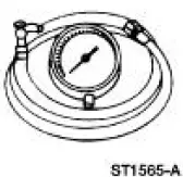 |
Transmission Fluid Pressure Gauge 307-004 (T57L-77820-A) |
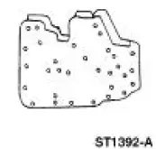 |
Air Test Plate, Transmission 307-246 (T92P-7006-A) |
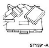 |
Breakout Box, EEC-V Control System 418-049 (T94L-50-EEC-V) or equivalent |
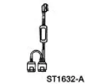 |
MLP-TR Cable 418-F107 (007-00111) or equivalent |
 |
Worldwide Diagnostic System (WDS) 418-F224 New Generation STAR (NGS) Tester 418-F052 or equivalent scan tool |
 |
Transmission Tester 307-F016 (007-00130) or equivalent |
 |
Trans Tester TR/MLP Overlay and Manual 007-00131 or equivalent |
 |
73 III Automotive Meter 105-R0057 or equivalent |
 |
UV Leak Detector Kit 164-R0756 or equivalent |
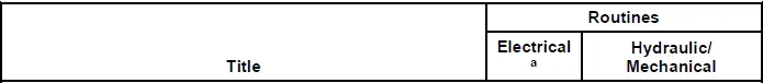
The Diagnosis by Symptom charts give the technician diagnostic information, direction, and suggest possible components, using a symptom as a starting point.
The Diagnosis by Symptom charts are divided into two categories: Electrical Routines, indicated by 200 series numbers, and Hydraulic/Mechanical Routines, indicated by 300 series numbers. The Electrical Routines list the possible electrical components that could cause or contribute to the symptom described. The Hydraulic/Mechanical Routines list the possible hydraulic or mechanical components that could cause or contribute to the symptom described.
Diagnosis by Symptom Chart Directions
1. Using the Diagnosis by Symptom Index, select the Concern/Symptom that best describes the condition.
2. Refer to the routine indicated in the Diagnosis by Symptom Index.
3. Always begin diagnosis of a symptom with:
a. preliminary inspections.
b. verifications of condition.
c. checking the fluid levels.
d. carrying out other test procedures as directed.
4. NOTE: Not all concerns and conditions with electrical components will set a diagnostic trouble code (DTC). Be aware that the components listed may still be the cause. Verify correct function of these components prior to proceeding to the Hydraulic/Mechanical Routine listed.
Begin with the Electrical Routine, if indicated. Follow the reference or action required statements. Always carry out the on-board diagnostic tests as required. Never skip steps.
Repair as required. If the concern is still present after electrical diagnosis, then proceed to the Hydraulic/Mechanical Routine listed.
5. The Hydraulic/Mechanical Routines list possible hydraulic or mechanical components that could cause the concern. These components are listed in the removal sequence and by most probable cause. All components listed must be inspected to ensure correct repair.
Diagnosis by Symptom Index
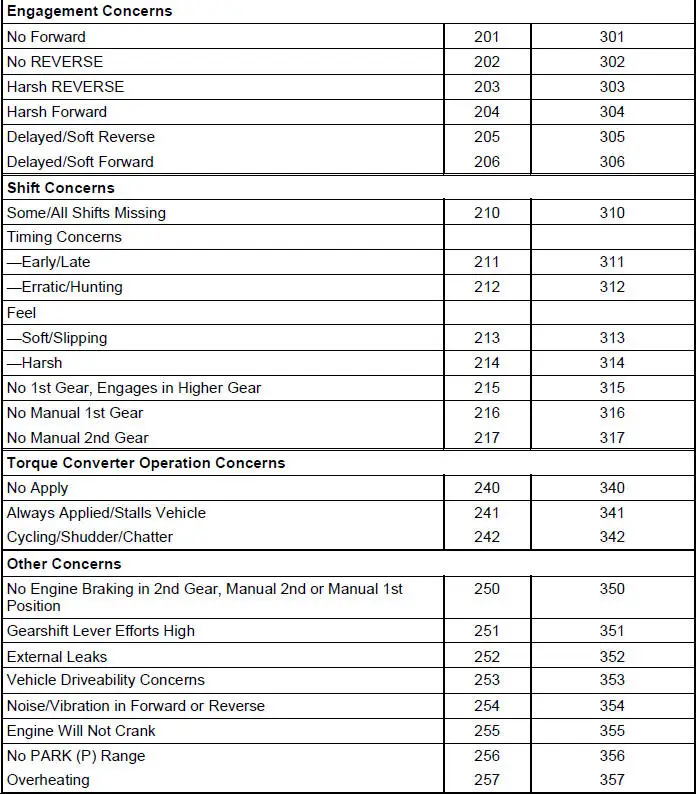
a - Carry out electrical routine first.
Diagnostic Routines
Engagement Concern: No Forward
| Possible Component | Reference/Action |
| 201 - ELECTRICAL ROUTINE | |
| No Electrical Concerns | |
| 301 - HYDRAULIC/MECHANICAL ROUTINE | |
| Fluid | |
| Incorrect level | Adjust fluid to correct level. Inspect as under Fluid Condition Check; refer to Verification of Condition. |
| Condition | |
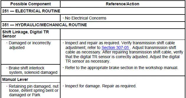
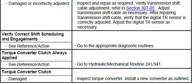
| Shift Linkage | Inspect and repair as required. Verify transmission shift cable adjustment; refer to Section. Adjust transmission shift cable as necessary. After repairing transmission shift cable, verify the digital transmission range (TR) sensor is correctly adjusted. Adjust the digital TR sensor as necessary. |
| Damaged or incorrectly adjusted | |
| Incorrect Pressures | Check pressure at line and forward clutch tap. Refer to Line Pressure Chart for specification. If pressures are low, check the following components: oil filter and seal assembly, main controls, pump assembly, forward clutch assembly. |
| Low forward clutch pressure, low line pressure | |
| Fluid Filter and Seal Assembly | |
| Plugged, damaged | Install a new filter and seal assembly. |
| Filter seal damaged | |
| Main Controls | |
| 3-4 shift valve, main regulator valve, manual valve - stuck, damaged | Inspect for damage. Repair as required. |
| Bolts not tightened to specifications | Tighten bolts to specifications. |
| Gaskets damaged | Inspect gaskets for damage and install a new gasket. |
| 2-3 accumulator and seals damaged | Inspect piston, seals and bore for damage.
Repair as required. Inspect the diameter for wear. |
| Pressure regulator valve | |
| Pump Assembly | |
| Bolts not tightened to specifications | Tighten bolts to specifications. |
| Porosity/cross leaks/ball missing or leaking, plugged hole | Inspect for porosity and leaks. Repair as required. |
| No. 3 and No. 4 seal rings damaged | Inspect seals for damage. Repair as
required. Inspect for damage and install a new gasket. |
| Gaskets damaged | |
| Forward Clutch Assembly | |
| Seals, piston damaged | Inspect seals for damage. Repair as required. |
| Check balls damaged, missing, mislocated, not seating correctly | Inspect for mislocation, poor seating,
damage. Install a new cylinder
as required. Check for abnormal wear, damage. Repair as required. |
| Friction elements damaged or worn | |
| One-Way Clutch Assembly (Planetary) | Inspect for damage. Repair as required. |
| Worn, damaged or assembled incorrectly | |
| Output Shaft | Inspect for damage. Install new components as required. |
| Damaged | |
Engagement Concern: No Reverse
| Possible Component | Reference/Action |
| 202 - ELECTRICAL ROUTINE | |
| No Electrical Concerns | |
| 302 - HYDRAULIC/MECHANICAL ROUTINE | |
| Fluid | |
| Incorrect level | Adjust fluid to correct level. Inspect as under Fluid Condition Check; refer to Verification of Condition. |
| Condition | |
| Shift Linkage | Inspect and repair as required. Verify transmission shift cable adjustment; refer to Section. Adjust transmission shift cable as necessary. After repairing transmission shift cable, verify the digital transmission range (TR) sensor is correctly adjusted. Adjust the digital TR sensor as necessary. |
| Damaged or incorrectly adjusted | |
| Incorrect Pressures | Check pressure at line and forward clutch tap. Refer to Line Pressure Chart for specification. If pressures are low, check the following components: oil filter and seal assembly, main controls, pump assembly, forward clutch assembly. |
| Low forward clutch pressure, low line pressure | |
| Fluid Filter and Seal Assembly | |
| Plugged, damaged | Install a new filter and seal assembly. |
| Main Controls | |
| No. 6 shuttle ball, manual valve, main regulator valve, 1-2 accumulator seals stuck or damaged | Inspect for damage. Repair as required. |
| Loose bolts | Tighten bolts to specifications. Inspect gaskets for damage and install a new gasket. |
| Gasket damaged | |
| Low/Reverse Servo | |
| Seals (piston and cover) damaged | Inspect for damage. Repair as required. |
| Servo cover retaining ring damaged | |
| Anchor pins (case) damaged | |
| Pump Assembly | |
| Loose bolts | Tighten bolts to specifications. |
| Porosity/cross leaks/ball missing or leaking, plugged hole | Inspect for porosity and leaks. Repair as required. |
| No. 1 and No. 2 seal rings damaged | Inspect seals for damage. Repair as
required. Inspect for damage and install a new gasket. |
| Gaskets damaged | |
| Reverse Clutch Assembly | |
| Seals, piston damaged | Inspect seals for damage. Repair as required. |
| Check ball missing or damaged | |
| Friction elements damaged or worn | |
| Low/Reverse Band | Inspect for damage. Repair as required. |
| Band, servo, anchor pins damaged or worn | |
Engagement Concern: Harsh Reverse
| Possible Component | Reference/Action |
| 203 - ELECTRICAL ROUTINE | |
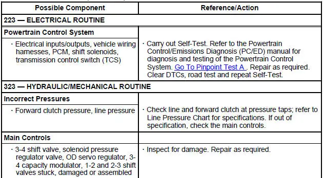
| Powertrain Control System | Carry out Self-Test; refer to the Powertrain Control/Emissions Diagnosis (PC/ED) manual for diagnosis and testing of the Powertrain Control System. Carry out engagement test, EPC test and Go To Pinpoint Test B or Go To Pinpoint Test D . Check idle speed. Repair as required. Clear DTCs, road test and repeat Self- Test. |
| Electrical inputs/outputs, vehicle wiring harnesses, PCM, TFT sensor, EPC solenoid | |
| 303 - HYDRAULIC/MECHANICAL ROUTINE | |
| Fluid | |
| Incorrect level | Adjust fluid to correct level. |
| Condition | Inspect condition of fluid. |
| Engine Driveline | |
| Looseness in the driveshaft, U-joints or the engine mounts | Repair as required. |
| Shift Linkage | Inspect and repair as required. Verify transmission shift cable adjustment; refer to Section. Adjust transmission shift cable as necessary. After repairing transmission shift cable, verify the digital transmission range (TR) sensor is correctly adjusted. Adjust the digital TR sensor as necessary. |
| Damaged or incorrectly adjusted | |
| Incorrect Pressures | Check pressure at line and forward clutch tap. Refer to Line Pressure Chart for specification. If pressures are low, check the following components: oil filter and seal assembly, main controls, pump assembly, forward clutch assembly. |
| High line pressure, high EPC pressure | |
| Fluid Filter and Seal Assembly | |
| Plugged, damaged | Install a new filter and seal assembly. |
| Filter seal damaged | |
| Main Controls | |
| No. 6 shuttle ball, No. 5 check ball, manual valve, main regulator valve stuck, damaged or missing | Inspect for damage. Repair as required. |
| Bolts not tightened to specifications | Tighten bolts to specifications. |
| Gaskets damaged | Inspect gaskets for damage and install a
new gasket. Inspect for damage, contamination. Carry out EPC test in Routine No. 203. Repair as required. |
| EPC solenoid stuck or damaged | |
| Low Reverse Servo | |
| Seals (piston and cover) damaged | Inspect for damage. Repair as required. |
| Servo cover retaining ring assembled incorrectly | |
| Anchor pins (case) damaged | |
| Pump Assembly | |
| Bolts not tightened to specifications | Tighten bolts to specifications. |
| Porosity/cross leaks | Inspect pump assembly. Install new as required. |
| No. 1 and No. 2 seal rings damaged | Inspect seals for damage. Repair as
required. Inspect for damage and install a new gasket. |
| Gaskets damaged | |
| Reverse Clutch Assembly | |
| Seals, piston damaged | Inspect seals for damage. Repair as required. |
| Check ball missing or damaged | |
| Friction elements damaged or worn | |
| Low Reverse Band | Inspect for damage. Repair as required. |
| Band, servo, anchor pin damaged or worn | |
Engagement Concern: Harsh Forward
| Possible Component | Reference/Action |
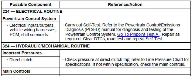
| 204 - ELECTRICAL ROUTINE | |
| Powertrain Control System | Carry out Self-Test; refer to the Powertrain Control/Emissions Diagnosis (PC/ED) manual for diagnosis and testing of the Powertrain Control System. Carry out engagement test, EPC test and Go To Pinpoint Test B or Go To Pinpoint Test D . Check idle speed. Repair as required. Clear DTCs, road test and repeat Self- Test. |
| Electrical inputs/outputs, vehicle wiring harnesses, PCM, TFT sensor, EPC solenoid | |
| 304 - HYDRAULIC/MECHANICAL ROUTINE | |
| Fluid | |
| Incorrect level | Adjust fluid to correct level. |
| Condition | Inspect condition of fluid. |
| Engine Driveline | |
| Looseness in the driveshaft, U-joints or the engine mounts | Repair as required. |
| Incorrect Pressures | Check pressure at line and forward clutch tap. Refer to Line Pressure Chart for specification. If pressures are low, check the following components: oil filter and seal assembly, main controls, pump assembly, forward clutch assembly. |
| High forward clutch pressure, high line pressure, high EPC pressure | |
| Main Controls | |
| Main regulator valve stuck, damaged | Inspect and repair as required. |
| Bolts not tightened to specifications | Tighten bolts to specifications. |
| Gaskets damaged | Inspect gaskets for damage and install a
new gasket. Inspect for damage, contamination. Carry out EPC test in Routine No. 204. Repair as required. |
| EPC solenoid stuck or damaged | |
| Case | |
| 2-3 accumulator seal/retainer stuck, damaged | Inspect for damage. Repair as required. |
| Pump Assembly | |
| Bolts not tightened to specifications | Tighten bolts to specifications. |
| Porosity/cross leaks | Inspect pump assembly. Install new as required. |
| Gaskets damaged | Inspect for porosity/leaks. Install a new pump as
required. Inspect for damage and install a new gasket. |
| Forward Clutch Assembly | |
| Check ball missing or damaged | Inspect for mislocation, poor seating, damage. Install a new forward clutch cylinder. |
| Friction elements damaged or worn | Inspect for damage. Repair as required. |
| Forward clutch wave spring damaged | Inspect for damage. Repair as required. Inspect for damage. Repair as required. |
| Forward clutch return spring damaged | |
Engagement Concern: Delayed/Soft Reverse
| Possible Component | Reference/Action |
| 205 - ELECTRICAL ROUTINE | |
| No Electrical Concerns | |
| 305 - HYDRAULIC/MECHANICAL ROUTINE | |
| Fluid | |
| Incorrect level | Adjust fluid to correct level. Inspect condition of fluid. |
| Condition | |
| Shift Linkage | Inspect and repair as required. Verify transmission shift cable adjustment; refer to Section. Adjust transmission shift cable as necessary. After repairing transmission shift cable, verify the digital transmission range (TR) sensor is correctly adjusted. Adjust the digital TR sensor as necessary. |
| Damaged or incorrectly adjusted | |
| Incorrect Pressures | Check pressure at line tap; refer to Line Pressure Chart for specifications. If pressures are low, check the following components: main controls, pump assembly, reverse clutch assembly, reverse servo. |
| Low reverse clutch pressure, low reverse band pressure, low line pressure | |
| Fluid Filter and Seal Assembly | |
| Plugged, damaged | Install a new filter and seal assembly. Filter seal damaged |
| Main Controls | |
| No. 6 shuttle ball, manual valve, main regulator valve stuck or damaged | Inspect for damage. Repair as required. |
| Bolts not tightened to specifications | Tighten bolts to specifications. Inspect for damage and install a new gasket. |
| Gaskets damaged | |
| Case | Inspect for damage. Repair as required. |
| 1-2 accumulator seals stuck or damaged | |
| Low Reverse Servo | |
| Seals (piston and cover) damaged | Inspect for damage. Repair as required. |
| Servo cover retaining ring assembled incorrectly | |
| Pump Assembly | |
| Bolts not tightened to specifications | Tighten bolts to specifications. |
| Porosity/cross leaks/ball missing or leaking | Inspect pump assembly. Install new as required. |
| No. 1 and No. 2 seal rings damaged | Inspect seals for damage. Repair as
required. Inspect for damage and install a new gasket. |
| Gaskets damaged | |
| Reverse Clutch Assembly | |
| Seals, piston damaged | Inspect seals for damage. Repair as required. |
| Check ball missing or damaged | |
| Friction elements damaged or worn | |
| Low Reverse Band | Inspect for damage. Repair as required. |
| Damaged, worn | |
Engagement Concern: Delayed/Soft Forward
| Possible Component | Reference/Action |
| 206 - ELECTRICAL ROUTINE | |
| No Electrical Concerns | |
| 306 - HYDRAULIC/MECHANICAL ROUTINE | |
| Fluid | |
| Incorrect level | Adjust fluid to correct level. Inspect condition of fluid. |
| Condition | |
| Shift Linkage | Inspect and repair as required. Verify transmission shift cable adjustment; refer to Section. Adjust transmission shift cable as necessary. After repairing transmission shift cable, verify the digital transmission range (TR) sensor is correctly adjusted. Adjust the digital TR sensor as necessary. |
| Damaged or incorrectly adjusted | |
| Incorrect Pressures | Check pressure at line, forward clutch and EPC taps; refer to Line Pressure Chart for specifications. If pressures are low, check the following components: oil filter and seal assembly, main controls and pump assembly. |
| Low forward clutch pressure, low line pressure, low EPC pressure | |
| Fluid Filter and Seal Assembly | |
| Plugged, damaged | Install a new filter and seal assembly.
|
| Filter seal damaged | |
| Main Controls | |
| 3-4 shift valve, main regulator valve stuck or damaged | Inspect and repair as required. |
| Bolts not tightened to specifications | Tighten bolts to specifications. Inspect for damage and repair as required. |
| Gaskets damaged | |
| Case | Inspect for damage. Repair as required. |
| 2-3 or 1-2 accumulator, bore damaged or stuck | |
| Low Reverse Servo | |
| Seals (piston and cover) damaged | Inspect for damage. Repair as required. |
| Servo cover retaining ring assembled incorrectly | |
| Pump Assembly | |
| Bolts not tightened to specifications | Tighten bolts to specifications. |
| Porosity/cross leaks | Inspect pump assembly. Repair as required. |
| No. 3 and No. 4 seal rings damaged | Inspect for damage. Repair as required. Inspect for damage. Repair as required. |
| Gaskets damaged | |
| Forward Clutch Assembly | |
| Seals, piston damaged | Inspect for damage. Repair as required |
| Check ball missing or damaged | Inspect for mislocation, poor seating,
damage. Install a new cylinder
as required. Check for damage. Repair as required. |
| Friction elements damaged or worn | |
Shift Concerns: Some/All Shifts Missing
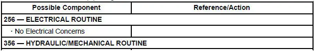
| Possible Component | Reference/Action |
| 210 - ELECTRICAL ROUTINE | |
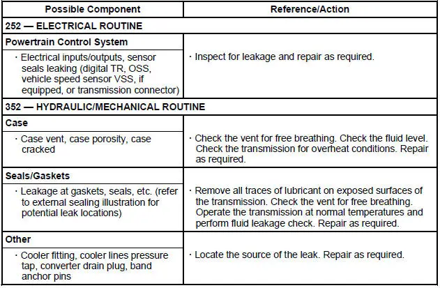
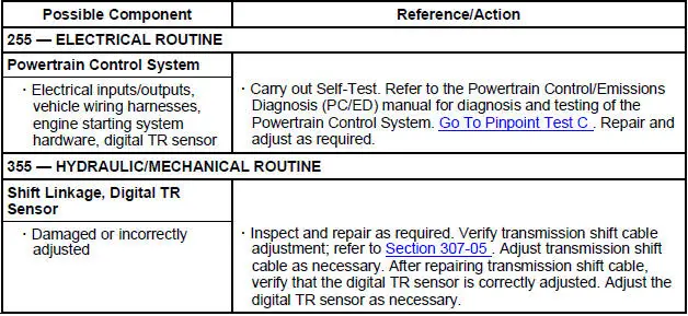
| Powertrain Control System | Carry out Self-Test; refer to the Powertrain Control/Emissions Diagnosis (PC/ED) manual for diagnosis and testing of the Powertrain Control System. Go To Pinpoint Test A , Go To Pinpoint Test C or Go To Pinpoint Test E . Repair as required. Clear DTCs, road test and repeat Self-Test. |
| Electrical inputs/outputs, vehicle wiring harnesses, PCM, shift solenoids, output shaft speed (OSS) sensor, digital TR sensor | |
| 303 - HYDRAULIC/MECHANICAL ROUTINE | |
| Fluid | |
| Incorrect level | Adjust fluid to correct level. |
| Condition | Inspect condition of fluid. |
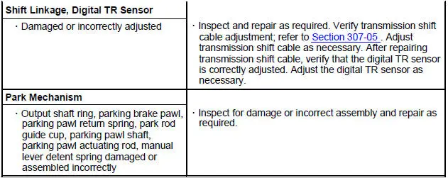
| Shift Linkage, Digital TR Sensor | Inspect and repair as required. Verify
transmission shift cable
adjustment; refer to Section. Adjust transmission shift
cable as necessary. After repairing transmission shift cable,
verify that the digital TR sensor is correctly adjusted. Adjust
the digital TR sensor as necessary. Refer to the following shift routine(s) for further diagnosis:
|
| Damaged or incorrectly adjusted | |
Shift Concerns: Timing Concerns - Early/Late
| Possible Component | Reference/Action |
| 211 - ELECTRICAL ROUTINE | |
| Powertrain Control System | Carry out Self-Test. Refer to the
Powertrain Control/Emissions
Diagnosis (PC/ED) manual for diagnosis and testing of the
Powertrain Control System. Go To Pinpoint Test A , Go To
Pinpoint Test C or Go To Pinpoint Test E . Repair as required.
Clear DTCs, road test and repeat Self-Test. |
| Electrical inputs/outputs, vehicle wiring harnesses, PCM, shift solenoids, EPC solenoid, TFT sensor, OSS | |
| 311 - HYDRAULIC/MECHANICAL ROUTINE | |
| Other | |
| Tire size change, axle ratio change | Verify vehicle has original equipment. Refer to Certification Label and Safety Standard Certification Label. Changes in tire size or axle ratio will affect shift timing. |
| Fluid | |
| Incorrect level | Adjust fluid to correct level. |
| Condition | Inspect condition of fluid. |
| Powertrain Control System | |
| Engine driveability concerns | Refer to Routine 253. |
| Incorrect Pressures | Check pressure at line and EPC taps; refer
to Line Pressure
Chart for specifications. If not OK, check the main controls. If
OK, refer to the shift routine(s) for further diagnosis:
|
| Line pressure, EPC pressure | |
| Main Controls | |
| EPC solenoid, stuck or damaged hydraulically or mechanically | Inspect for damage, contamination. Carry out EPC tests in Routine No. 211. Repair as required. |
| Valves, accumulators, seals stuck or damaged or assembled incorrectly | Inspect for damage. Repair as required. |
| Gaskets damaged | Inspect for damage and install a new
gasket. Clean or install a new screen. |
| Solenoid screen blocked or damaged | |
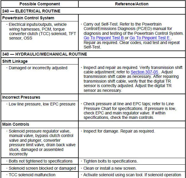
Shift Concerns: Timing Concerns - Erratic/Hunting
| Possible Component | Reference/Action |
| 212 - ELECTRICAL ROUTINE | |
| Powertrain Control System | Carry out Self-Test. Refer to the Powertrain Control/Emissions Diagnosis (PC/ED) manual for diagnosis. Go To Pinpoint Test A , Go To Pinpoint Test C or Go To Pinpoint Test E . Repair as required. Clear DTCs, road test and repeat Self-Test. |
| Electrical inputs/outputs, vehicle wiring harnesses, PCM, shift solenoids, torque converter clutch (TCC) solenoid, digital TR sensor, output shaft speed (OSS) | |
| 312 - HYDRAULIC/MECHANICAL ROUTINE | |
| Fluid | |
| Incorrect level | Adjust fluid to correct level. Inspect condition of fluid. |
| Condition | |
| Main Controls | |
| Valves, accumulators, seals, assembled wrong, stuck or damaged | Inspect for damage. Repair as required. |
| Solenoid screen blocked or damaged | Inspect gaskets for damage and install a
new gasket. Clean or install a new screen. |
| Gaskets damaged | |
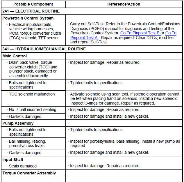
| Torque Converter Clutch | Refer to Torque Converter Operation Concerns: Cycling/Shudder/Chatter Hydraulic/Mechanical Routine 342. |
| Torque converter | |
| Specific Shifts | Refer to the following shift routine(s)
for further diagnosis:
|
Shift Concerns: Feel - Soft/Slipping
| Possible Component | Reference/Action |
| 213 - ELECTRICAL ROUTINE | |
| Powertrain Control System | Carry out Self-Test. Refer to the
Powertrain Control/Emissions
Diagnosis (PC/ED) manual for diagnosis and testing of the
Powertrain Control System. Go To Pinpoint Test D or Go To
Pinpoint Test E . Repair as required. Clear DTCs, road test and
repeat Self-Test. Refer to Routine 253. |
| Electrical inputs/outputs, vehicle wiring harnesses, PCM, EPC solenoid, OSS | |
| Engine driveability concerns | |
| 313 - HYDRAULIC/MECHANICAL ROUTINE | |
| Fluid | |
| Incorrect level | Adjust fluid to correct level. |
| Condition | Inspect condition of fluid. |
| Incorrect Pressures | Check pressures at line and EPC taps;
refer to Line Pressure
Chart for specifications. If pressures are low or all shifts are
soft/slipping, go to main controls. If pressures are OK and a
specific shift is soft/slipping, refer to the following routine(s) for
further diagnosis:
|
| Low line pressure, low EPC pressure | |
| Main Controls | |
| Main regulator valve, overdrive servo regulator valve stuck, damaged or assembled incorrectly | Inspect for damage. Repair as required. Inspect for damage and contamination. Carry out EPC tests in Routine 213. Repair as required. |
| EPC solenoid stuck or damaged | |
| Case | |
| 1-2 accumulator stuck or damaged | Inspect for damage. Repair as required. |
| Filter and Seal Assembly | Inspect for damage. Install a new filter as required. Inspect for damage. Repair as required. |
| Filter plugged, damaged | |
| Seal damaged or cut | |
Shift Concerns: Feel - Harsh
| Possible Component | Reference/Action |
| 214 - ELECTRICAL ROUTINE | |
| Powertrain Control System | Carry out Self-Test. Refer to the
Powertrain Control/Emissions
Diagnosis (PC/ED) manual for diagnosis and testing of the
Powertrain Control System. Go To Pinpoint Test D or Go To
Pinpoint Test E . Repair as required. Clear DTCs, road test and
repeat Self-Test. Refer to Routine 253. |
| Electrical inputs/outputs, vehicle wiring harnesses, PCM, EPC solenoid, OSS | |
| Engine driveability concerns | |
| 314 - HYDRAULIC/MECHANICAL ROUTINE | |
| Fluid | |
| Incorrect level | Adjust fluid to correct level. |
| Condition | Inspect condition of fluid. |
| Incorrect Pressures | Check pressures at line and EPC taps;
refer to Line Pressure
Chart for specifications. If pressures are low or all shifts are
soft/slipping, go to main controls. If pressures are OK and a
specific shift is soft/slipping, refer to the following routine(s) for
further diagnosis:
|
| High line pressure, high EPC pressure | |
| Main Controls | |
| Main regulator valve, overdrive servo regulator valve stuck, damaged or assembled incorrectly | Inspect for damage. Repair as required.
Inspect for damage or contamination. Carry out EPC tests in Routine 214. Repair as required. |
| EPC solenoid stuck or damaged | |
Shift Concerns: No 1st Gear, Engages In Higher Gear
| Possible Component | Reference/Action |
| 215 - ELECTRICAL ROUTINE | |
| Powertrain Control System | Carry out Self-Test. Refer to the Powertrain Control/Emissions Diagnosis (PC/ED) manual for diagnosis and testing of the Powertrain Control System. Go To Pinpoint Test A or Go To Pinpoint Test C . Repair as required. Clear DTCs, road test and repeat Self-Test. |
| Electrical inputs/outputs, vehicle wiring harnesses, PCM, shift solenoids, digital transmission range TR sensor | |
| 315 - HYDRAULIC/MECHANICAL ROUTINE | |
| Shift Linkage, Digital TR Sensor | |
| Damaged or incorrectly adjusted | Inspect and repair as required. Verify transmission shift cable adjustment. Refer to Section. Adjust transmission shift cable as necessary. After repairing transmission shift cable, verify that the digital TR sensor is correctly adjusted. |
| Incorrect Pressures | Check for which pressures are on and refer to Band/Clutch Application Chart 601 and corresponding routines.
|
Low reverse clutch pressure,
low reverse band pressure, low
line pressure
|
|
| Mechanical | |
| Bands, clutches or seals damaged or worn | Refer to Transmission Disassembly and Assembly. |
X = pressure applied
Shift Concerns: No Manual 1st Gear
| Possible Component | Reference/Action |
| 216 - ELECTRICAL ROUTINE | |
| Powertrain Control System | Carry out Self-Test. Refer to the
Powertrain
Control/Emissions Diagnosis (PC/ED) manual for diagnosis
and testing of the Powertrain Control System. Go To Pinpoint
Test A or Go To Pinpoint Test C . Repair as required. Clear
DTCs, road test and repeat Self-Test.
|
| Electrical inputs/outputs, vehicle wiring harnesses, PCM, shift solenoids, digital TR sensor | |
| 316 - HYDRAULIC/MECHANICAL ROUTINE | |
| Shift Linkage, Cable, Digital TR Sensor | |
| Damaged or incorrectly adjusted | Inspect and repair as required. Verify transmission shift cable adjustment; refer to Section. Adjust transmission shift cable as necessary. After repairing transmission shift cable, verify that the digital TR sensor is correctly adjusted. Adjust the digital TR sensor as necessary. |
| Incorrect Pressures | Check pressure at line and EPC pressure taps; refer to Line Pressure Chart for specifications. If pressures are low, check the following components: oil filter and seal assembly, main controls, reverse clutch assembly and reverse servo assembly. |
| Low reverse clutch pressure, low reverse band pressure, low line pressure, low EPC pressure | |
| Main Controls | |
| No. 6 shuttle ball, manual valve, main regulator valve, low servo modulator valve stuck, damaged or assembled incorrectly | Inspect for damage. Repair as required.
Tighten bolts to specifications. |
| Bolts not tightened to specifications | |
| Fluid Filter and Seal Assembly | |
| Plugged or damaged | Install a new filter and seal assembly. |
| Low Reverse Servo | Inspect for damage. Repair as required.
|
| Seals (piston and cover) damaged | |
Shift Concerns: No Manual 2nd Gear
| Possible Component | Reference/Action |
| 217 - ELECTRICAL ROUTINE | |
| Powertrain Control System | Carry out Self-Test. Refer to the
Powertrain Control/Emissions
Diagnosis (PC/ED) manual for diagnosis and testing of the
Powertrain Control System. Go To Pinpoint Test A or Go To
Pinpoint Test C . Repair as required. Clear DTCs, road test
and repeat Self-Test.
|
| Electrical inputs/outputs, vehicle wiring harnesses, PCM, shift solenoids, digital TR sensor | |
| 317 - HYDRAULIC/MECHANICAL ROUTINE | |
| Shift Linkage, Cable, Digital TR Sensor | |
| Damaged or incorrectly adjusted | Inspect and repair as required. Verify transmission shift cable adjustment; refer to Section. Adjust transmission shift cable as necessary. After repairing transmission shift cable, verify that the digital TR sensor is correctly adjusted. Adjust the digital TR sensor as necessary. |
| Main Controls | |
| 3-4 shift valve, 1-2 and 2-3 shift valve, 3-4 capacity modulator valve stuck, damaged or assembled incorrectly | Inspect for damage. Repair as required.
Tighten bolts to specifications. |
| Bolts not tightened to specifications | |
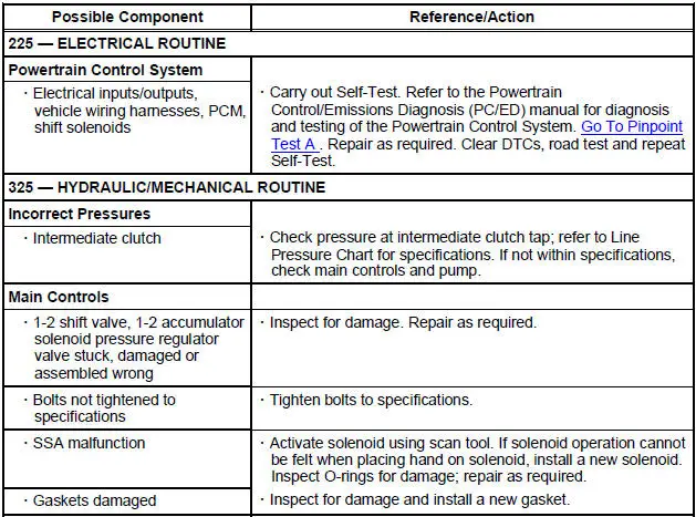
Shift Concerns: 1-2 Shift (Automatic)
| Possible Component | Reference/Action |
| 220 - ELECTRICAL ROUTINE | |
| Powertrain Control System | Carry out Self-Test. Refer to the Powertrain
Control/Emissions
Diagnosis (PC/ED) manual for diagnosis and testing of the
Powertrain Control System. Go To Pinpoint Test D or Go To
Pinpoint Test E . Repair as required. Clear DTCs, road test and
repeat Self-Test. Refer to Routine 253. |
| Electrical inputs/outputs, vehicle wiring harnesses, PCM, EPC solenoid, OSS | |
| Engine driveability concerns | |
| 320 - HYDRAULIC/MECHANICAL ROUTINE | |
| Shift Linkage, Digital TR Sensor | |
| Damaged or incorrectly adjusted | Inspect and repair as required. Verify transmission shift cable adjustment; refer to Section. Adjust transmission shift cable as necessary. After repairing transmission shift cable, verify that the digital TR sensor is correctly adjusted. Adjust the digital TR sensor as necessary. |
| Incorrect Pressures | Check pressure at line and intermediate clutch taps; see the line pressure chart for specifications. If not OK, check the main controls. |
| Intermediate clutch pressure, line pressure | |
| Main Controls | |
| 1-2 shift valve, stuck or damaged | Inspect for damage. Repair as required. Tighten bolts to specification. |
| Bolts not tightened to specifications | |
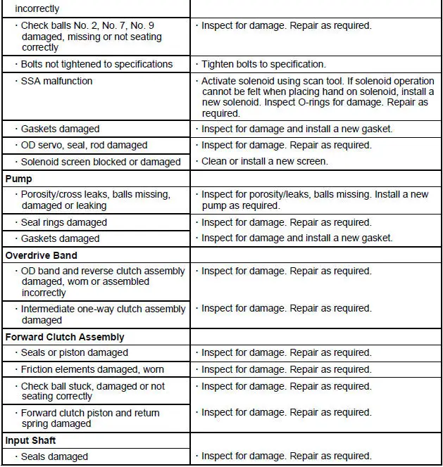
| Shift solenoid SSA malfunction | Activate solenoid using scan tool. If solenoid operation cannot be felt when placing hand on solenoid, install a new solenoid. Inspect O-rings for damage. Repair as required. |
| Gasket damaged | Inspect for damage and install a new
gasket. Inspect for damage. Repair as required. |
| No. 8 ball not seating | |
| Case | |
| 1-2 accumulator stuck or damaged | Inspect for damage. Repair as required. |
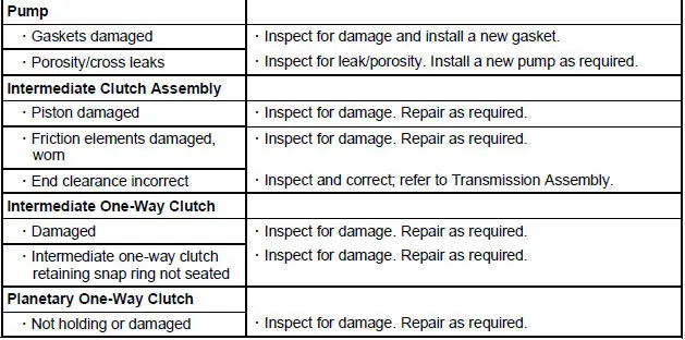
| Pump | Inspect for porosity/leaks, balls missing. Install a new pump as required. Inspect for damage and install a new gasket. |
| Porosity/cross leaks, balls missing, damaged or leaking | |
| Gasket damaged | |
| Intermediate Clutch Assembly | Inspect for damage. Repair as required. Inspect for damage. Repair as required. Inspect for damage. Repair as required. |
| Seals damaged | |
| Piston damaged Friction elements damaged or worn |
|
| Intermediate One-Way Clutch Assembly | Inspect for damage. Repair as required. |
| Not holding or damaged | |
| Planetary One-Way Clutch Assembly | |
| Not overrunning or damaged | Inspect for damage. Repair as required. |
| 1-2 Accumulator | Inspect for damage. Repair as required. Inspect for damage. Repair as required. |
| Damaged accumulator piston | |
| Springs damaged or broken | |
| Case bore scored | Inspect for damage. Repair as required. |
Shift Concerns: 2-3 Shift (Automatic)
| Possible Component | Reference/Action |
| 221 - ELECTRICAL ROUTINE | |
| Powertrain Control System | Carry out Self-Test. Refer to the Powertrain
Control/Emissions
Diagnosis (PC/ED) manual for diagnosis and testing of the
Powertrain Control System. Go To Pinpoint Test D or Go To
Pinpoint Test E . Repair as required. Clear DTCs, road test and
repeat Self-Test. Refer to Routine 253. |
| Electrical inputs/outputs, vehicle wiring harnesses, PCM, EPC solenoid, OSS | |
| Engine driveability concerns | |
| 321 - HYDRAULIC/MECHANICAL ROUTINE | |
| Shift Linkage, Digital TR Sensor | |
| Damaged or incorrectly adjusted | Inspect and repair as required. Verify transmission shift cable adjustment; refer to Section. Adjust transmission shift cable as necessary. After repairing transmission shift cable, verify that the digital TR sensor is correctly adjusted. Adjust the digital TR sensor as necessary. |
| Incorrect Pressures | Check pressure at line and intermediate clutch taps; see the line pressure chart for specifications. If not OK, check the main controls. |
| Intermediate clutch pressure, line pressure | |
| Main Controls | |
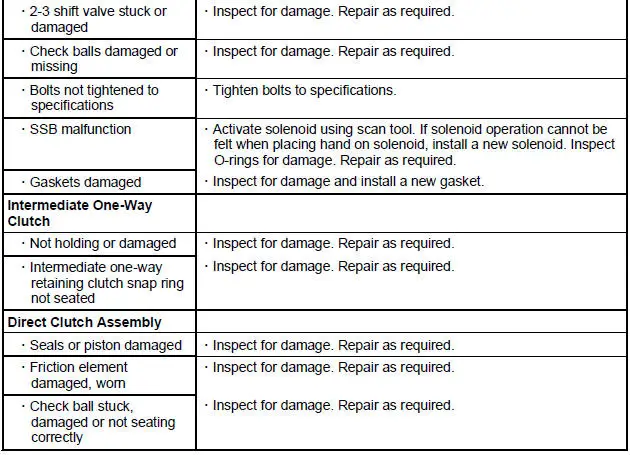
| 2-3 shift valve, check ball No.
9 or No. 3, solenoid pressure regulator valve, damaged or assembled incorrectly |
Inspect for damage. Repair as required.
Tighten bolts to specification. |
| Bolts not tightened to specifications | |
| Shift solenoid SSB malfunction | Activate solenoid using scan tool. If solenoid
operation cannot
be felt when placing hand on solenoid, install a new solenoid.
Inspect O-rings for damage. Repair as required. |
| Gasket damaged | Inspect for damage and install a new
gasket. Inspect for damage. Repair as required. |
| Output shaft seals damaged or cup plug leaking or missing | |
| Case | |
| Output shaft rear seals leaking or damaged | Inspect for damage. Repair as required. Inspect case for damaged seal area. If damaged, install a new case. |
| Intermediate One-Way Clutch Assembly | Inspect for damage. Repair as required. |
| Not overrunning or damaged | |
| Output Shaft | |
| Seal rings damaged | Inspect for damage. Repair as required. |
| Cup plug damaged or missing | |
| Direct Clutch Assembly | Inspect for damage. Repair as required. Inspect for damage. Repair as required. |
| Seals or piston damaged | |
| Friction elements worn or damaged | |
| Check ball not seating | Inspect for damage. Repair as required. Inspect for damage. Repair as required. |
| Return spring assembly damaged | |
| 2-3 Accumulator | Inspect for damage. Repair as required. Inspect for damage. Repair as required. |
| Damaged accumulator piston | |
| Springs damaged or broken | |
| Case bore scored | Inspect for damage. Repair as required. |
Shift Concerns: 3-4 Shift (Automatic)
Shift Concerns: 4-3 Shift (Automatic)
Shift Concerns: 3-2 Shift (Automatic)
Shift Concerns: 2-1 Shift (Automatic)
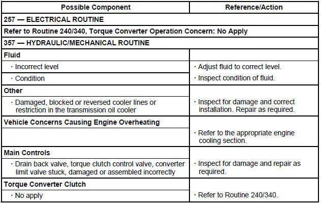
Torque Converter Clutch Operation Concerns: No Apply
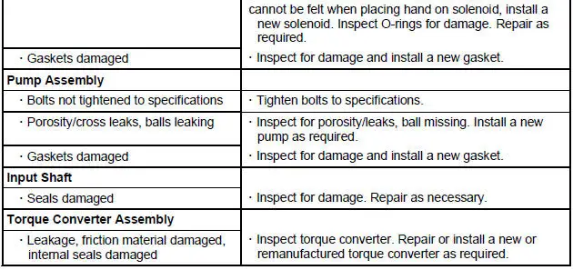
Torque Converter Clutch Operation Concerns: Always Applied/Stalls Vehicle
Torque Converter Clutch Operation Concerns: Cycling/Shudder/Chatter
Other Concerns: No Engine Braking In Manual 2nd Or Manual 1st Position
Other Concerns: Shift Lever Efforts High
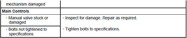
Other Concerns: External Leaks
Other Concerns: Poor Vehicle Performance
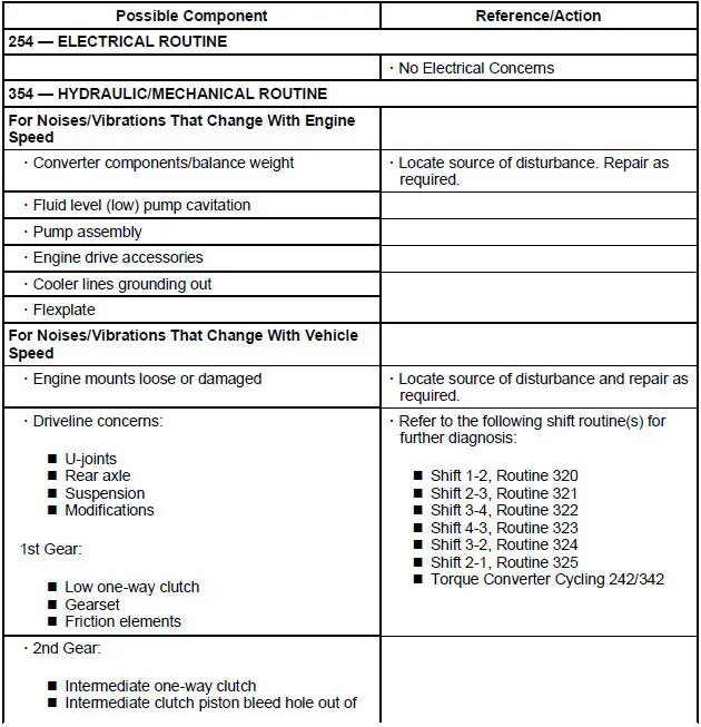
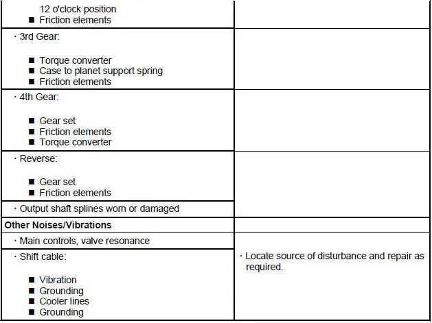
Other Concerns: Noise/Vibration - Forward Or Reverse
Other Concerns: Engine Will Not Crank
Other Concerns: No Park (P) Range
Other Concerns: Overheating
 Transmission Fluid Cooler
CAUTION: Whenever a transmission has been disassembled to install
new parts, the
cooler bypass valve (CBV), all transmission fluid coolers (in tank and
auxiliary) and
transmission fluid cooler l ...
 Transmission Fluid Cooler - Backflushing and Cleaning
1. CAUTION: Do not use any supplemental transmission fluid
additives or cleaning
agents. The use of these products could cause internal transmission
components to fail;
this will effect the oper ...
Other materials:
System menu features
Your system offers many menu features, such as allowing you to adjust
the touchscreen brightness, time and language, feedback and system
settings. You can access these options by pressing the MENU hard
button.
...
Engine (Removal)
Special Tool(s)
Lifting Bracket, Engine
303-D087 (D93P-6001-A1)
Lifting Bracket, Engine
303-D088 (D93P-6001-A2)
Spreader Bar
303-D089 (D93P-6001-A3)
Removal
All vehicles
1. Disconnect the battery ground cable. Fo ...
Axle Assembly
Removal and Installation
1. CAUTION: The vehicle must be on level ground and at curb height.
Mark the rear shock absorbers relative to their protective sleeve.
During installation, raise the suspension to this reference mark before
tightening the
suspens ...
