Ford Mustang (1999-2004) Service Manual: Disassembly
1. Remove the driveshaft (4602). For additional information, refer to Driveshaft in this section.
2. CAUTION: Under no circumstances is the driveshaft assembly to be clamped in the jaws of a vise or similar holding fixture. Denting or localizing fracture can result, causing driveshaft failure during vehicle operation.
Place the driveshaft (4602) on a suitable workbench. Be careful not to damage the tube.
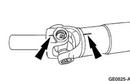
3. NOTE: If components are not marked and therefore installed incorrectly, driveline imbalance can occur.
Index-mark the driveshaft components.
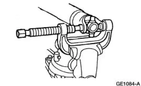
4. Clamp the special tool in a vise.
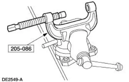
5. Remove all four of the snap rings.
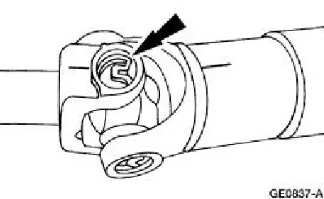
6. NOTE: If necessary, use a pair of pliers to remove a bearing cup if it cannot be pressed out all the way.
Remove the driveshaft slip yoke (4841).
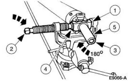
1. Position the driveshaft slip yoke in the U-joint tool.
2. Press out a bearing cup.
3. Rotate the driveshaft slip yoke.
4. Press on the spider to remove the remaining bearing cup.
5. Remove the driveshaft slip yoke.
7. Repeat Step 5 to remove the remaining bearing cups and spider from the driveshaft.
8. Clean the yoke area at each end of the driveshaft.
 Driveshaft Slip Yoke
Special Tool(s)
Installer/Remover, C Frame
and Screw
205-086 (T74P-4635-C)
...
 Assembly
1. NOTE: Universal joint service kits are to be installed as complete
assemblies only. Do not mix
components from other U-joint kits.
Install the bearing cup.
1. Start a new bearing cup into the d ...
Other materials:
Installation
1. CAUTION: Lubricate the filler pipe check valve area and the
tank-to-filler pipe
grommet with Serfactant prior to assembly or damage to the filler pipe check
valve will
occur.
NOTE: A new grommet must be used for the installation procedure due to
its dest ...
Battery (Removal and Installation)
Removal and Installation
WARNING: Batteries normally produce explosive gases which can
cause personal injury.
Therefore, do not allow flames, sparks or lighted substances to come
near the battery. When
charging or working near a battery, always sh ...
Navigation system
Your navigation system allows you to set a destination by using your
touchscreen or voice commands.
The navigation system contains map coverage for the United States,
Puerto Rico and U.S. Virgin Islands, Canada and Mexico.
Disclaimer
A disclaimer appears onc ...
