Ford Mustang (1999-2004) Service Manual: Assembly
1. NOTE: Universal joint service kits are to be installed as complete assemblies only. Do not mix components from other U-joint kits.
Install the bearing cup.
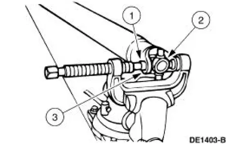
1. Start a new bearing cup into the driveshaft yoke.
- Check the needle bearings for correct positioning.
2. Position the new spider in the driveshaft yoke.
3. Using the special tool, press the bearing cup to just below the snap ring groove.
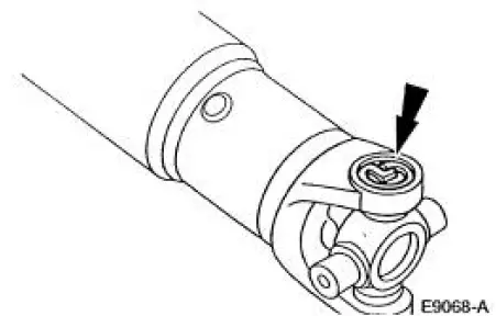
2. NOTE: Use the yellow snap rings supplied in the kit to assemble the universal joint (U-joint). If difficulty is encountered with the yellow snap rings, install the black snap rings, as required.
Remove the driveshaft from the special tool, and install the snap ring.
3. Repeat Steps 1 and 2 to install the opposite side of the driveshaft yoke.
4. Inspect the driveshaft slip yoke. Install new if necessary.
5. Repeat Steps 1 and 2 to install the remaining new bearing cups, spider, driveshaft slip yoke, and the snap rings.
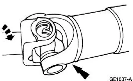
6. NOTE: Do not strike the bearings.
Check the U-joints for freedom of movement.
- If binding, strike the yoke with a brass or plastic hammer.
7. Install the driveshaft. For additional information, refer to Driveshaft in this section.
 Disassembly
1. Remove the driveshaft (4602). For additional information, refer to
Driveshaft in this section.
2. CAUTION: Under no circumstances is the driveshaft assembly to be
clamped in the
jaws of a vise o ...
 Universal Joint - Single Cardan, Flange Yoke
Special Tool(s)
Installer/Remover, C Frame
and Screw
205-086 (T74P-4635-C)
...
Other materials:
Transmission (Disassembly)
Special Tool(s)
Remover, Mainshaft Bearing
308-058 (T77J-7025-H)
Screw, Bearing Removal tube
308-092 (T84T-7025-B)
Holding Fixture, Transmission
307-003 (T57L-500-B)
Remover, Bushing
307-001 (TOOL-1175-AC) ...
Cable - Antenna Lead In
Removal
1. Remove the audio unit. Refer to Section.
2. Lower the glove compartment by releasing the stops from the
instrument panel.
3. Disconnect the antenna in-line connector.
4. Remove the antenna lead in cable.
1. Disconnect the pin-type ...
Latch - Door
Removal
1. Remove the door trim panel (23942). For additional information,
refer to Section.
2. Release the actuating rods by opening the clips.
3. Using a screwdriver, release the lock cylinder actuating rod.
4. Remove the door latch screws.
5. ...
