Ford Mustang (1999-2004) Service Manual: Removal
1. Disconnect the battery ground cable. For additional information, refer to Section.
2. Drain the engine cooling system. For additional information, refer to Section .
3. Remove the crankshaft pulley. For additional information, refer to Crankshaft Pulley in this section.
4. Remove the water pump pulley.
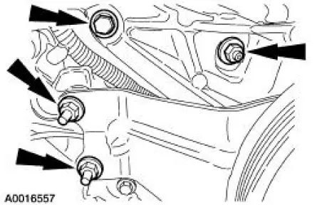
5. Remove the retainers and position the power steering pump aside.
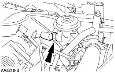
6. Disconnect the exhaust gas recirculation (EGR) tube.
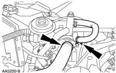
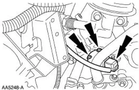
7. Disconnect the upper radiator hose and the bypass hose.
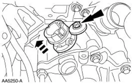
8. Remove the camshaft position (CMP) sensor.
9. Remove the heater water outlet tube. For additional information, refer to Section.
10. Remove the camshaft synchronizer assembly.
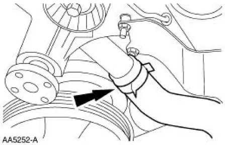
11. Disconnect the lower radiator hose.
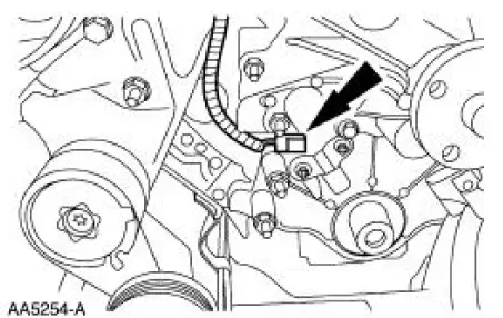
12. Disconnect the crankshaft position sensor electrical connector.
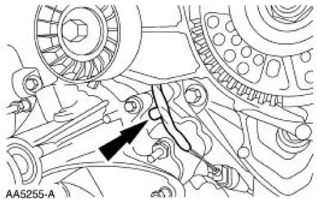
13. Remove the wiring harness pin-type retainer.
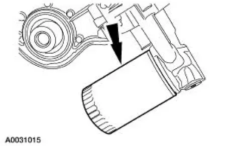
14. Remove the oil filter.
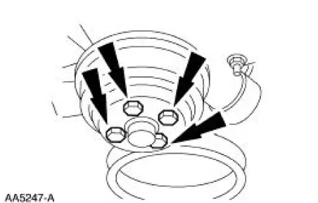
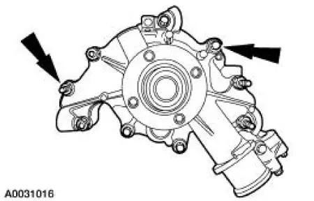
15. Remove the retainers and the water pump.
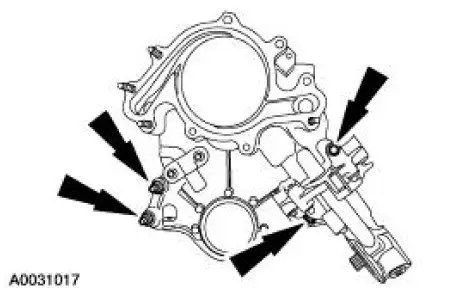
16. CAUTION: The cap screw is hidden; make sure to remove it or the engine front cover will be damaged.
NOTE: Record the location, type and size of the fasteners.
Remove the engine front cover.
- Slide the engine front cover off the two dowels.
- Remove and discard the engine front cover gasket.
 Engine Front Cover
Material
...
 Installation
1. CAUTION: In order to prevent foreign material from contaminating
the engine block
or the engine front cover it is necessary to seal the coolant and oil
passages of both
components. Failure to ...
Other materials:
Tracing Powder
Tracing powder is used to check both the uniformity of contact and the
tension of a seal against its
sealing surface. These tests are usually done when a suspected air leak/noise
appears to originate
from the seal area or during the alignment and adjustment ...
Driveshaft (Removal and Installation)
Material
Item
Specification
Threadlock and
Sealer
E0AZ-19554-AA
WSK-M2G351-A5 (type
II)
Removal and Installation
1. Raise and support the vehicle.
2. Carry out the following:
1. Place an index mark on the rear axle pinion flange and ...
Camshaft Runout
Special Tool(s)
Dial Indicator Gauge with
Holding Fixture
100-002 (TOOL-4201-C) or
equivalent
1. NOTE: Camshaft journals must be within specifications before
checking runout.
Use a Dial Indicator Gauge with Holding Fixture to measure the ...
