Ford Mustang (1999-2004) Service Manual: Disassembly
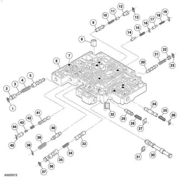
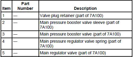
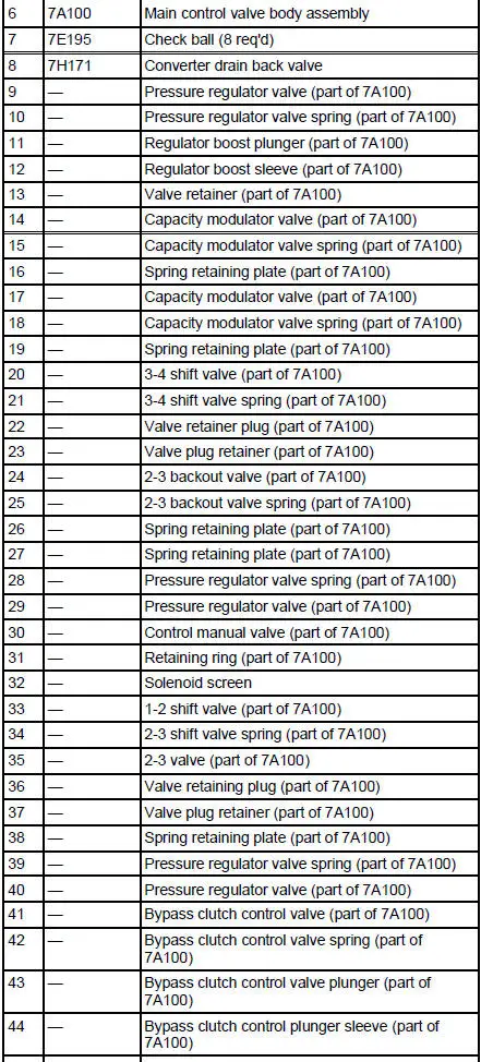
Main Control Valve Body - Disassembled View

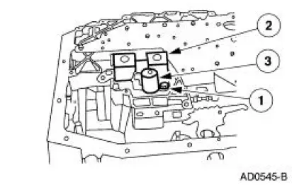
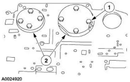
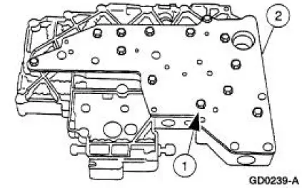
1. Remove the torque converter clutch (TCC) solenoid and the shift solenoid.
1. Remove the bolt.
2. Remove the shift solenoid.
3. Remove the TCC solenoid.
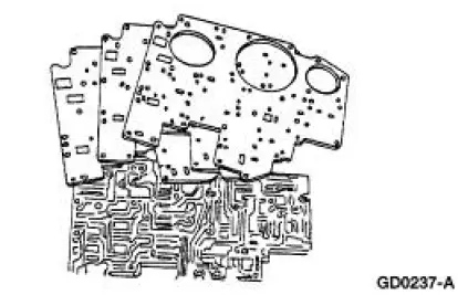
2. Remove the two reinforcement plates.
1. Remove the bolts.
2. Remove the plates.
3. Remove the separator plate and discard the gaskets.
4. NOTE: Note the location of the eight coasting booster valve shuttle balls for assembly.
Remove the eight coasting booster valve shuttle balls.
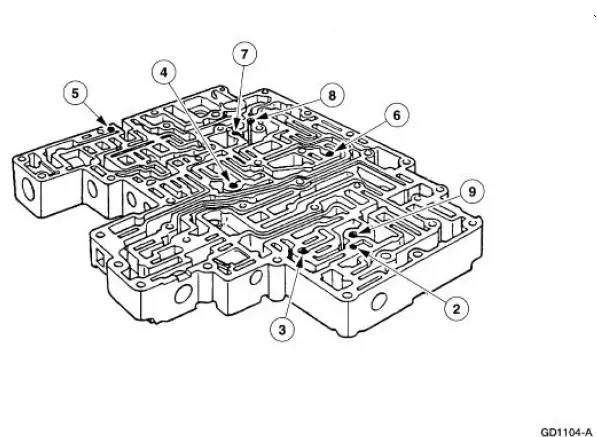
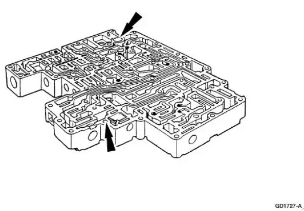
5. Remove the converter drain back valve and solenoid pressure supply screen.
6. Remove the main control valve body cover plate.
1. Remove the 13 bolts.
2. Remove the valve body cover plate and gasket.

 Assembly
1. CAUTION: Before beginning assembly, carry out and inspect the
following:
When building up subassemblies and assembling the transmission, ALWAYS use new
gaskets and seals.
All fasteners must be ti ...
Other materials:
Lamp Assembly - Fog Lamp (GT)
Removal
1. Raise and support the vehicle.
2. Remove the screw.
3. Partially lower the vehicle and remove the fog lamp assembly.
1. Disconnect the electrical connector.
2. Remove the two screws.
3. Remove the fog lamp assembly and replace the bul ...
Pinpoint Tests
PINPOINT TEST A: NO COMMUNICATION WITH THE INSTRUMENT
CLUSTER
Test Step
Result / Action to Take
A1 CHECK THE BATTERY POWER SUPPLY TO THE INSTRUMENT
CLUSTER
YesGO to A2 .
No
REPAIR the circuit.
TEST the system
for normal
operation.
...
Symptom Chart
Condition
Possible Sources
Action
Incorrect/erratic direction
of airflow from outlet(s)
No vacuum to A/C heater
function switch selector.
A/C heater function selector
switch leaks vacuum.
Kinked/pinched vacuu ...
