Ford Mustang (1999-2004) Service Manual: Driveline Angle Inspection
Special Tool(s)
|
|
Anglemaster II Driveline Inclinometer 164-R2402 or equivalent |
NOTE: An incorrect driveline angle can cause a vibration or shudder.
1. Check the vehicle for evidence or overload or sagging. Check for specified air pressures information in all four tires.
2. Normalize the suspension.
3. Drive the vehicle onto a drive-on hoist or back onto a front-end alignment rack.
4. Inspect the suspension and chassis. Verify that the vehicle curb position ride height is within specification.
- Measure the curb position ride height with the vehicle empty and all fluids full.
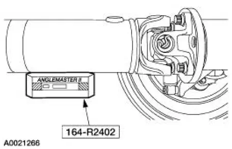
5. Place the Inclinometer flush against the bottom of the driveshaft. After the tool has been held on the driveshaft surface for 5 seconds, push the ALT ZERO button to calibrate to zero degrees.
Remove the tool.
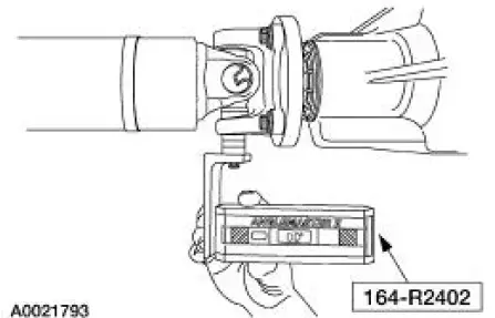
6. To check the pinion angle, rotate the driveshaft so that the rear axle pinion flange yoke ear is parallel to the floor. Remove the U-joint snap ring, then install the special tool. Check and record the pinion angle reading.
- If the angle is not within specification, repair or adjust to obtain the correct angle. Inspect the rear suspension, rear axle, rear axle mounting or the frame for wear or damage.
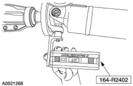
7. To check the engine angle, rotate the driveshaft so that the slip yoke ear is parallel to the floor.
Remove the U-joint snap ring, then install the special tool. Check and record the engine angle reading.
- If the angle is not within specifications, repair or adjust to obtain
the correct angles.
Inspect the powertrain/drivetrain mounts or frame rails for wear or damage.
 Component Tests
Driveline Vibration
An analysis of driveline vibration can also be conducted using the Vibration
Analyzer; follow the
manufacturer's directions.
Driveline vibration exhibits a higher frequency and l ...
 Axle Housing Casting Porosity (Holes in Casting) Repair
CAUTION: To keep the axle's sound characteristics, do not disassemble
the carrier.
NOTE: Casting porosity is a condition where occasionally gas bubbles will
form during the casting
process leaving s ...
Other materials:
Clutch And Clutch Field Coil
Special Tool(s)
2-Jaw Puller
205-D026 (D80L-1002-L) or
equivalent
Installer, A/C Compressor Coil
412-065 (T89P-19623-EH)
Holding Fixture, Compressor
Clutch (3.8L vehicles)
412-098 (T94P-19703-AH)
Holding ...
Transmission Fluid Drain and Refill
Special Tool(s)
Automatic Transmission Flush
and Fill Machine
211-00018
Automatic Transmission Flush
and Fill Machine
199-00010 or equivalent
Material
Item
Specification
MERCON V Automatic
Transmission Fluid
XT-5-QM
M ...
Spring Codes
The spring code portion of the vehicle certification (VC) label identifies
both the front and rear springs.
The first letter/number indicates the front spring code. The second
letter/number indicates the rear
spring code.
Front springs - base part numbe ...
