Ford Mustang (1999-2004) Service Manual: Component Tests
Driveline Vibration
An analysis of driveline vibration can also be conducted using the Vibration Analyzer; follow the manufacturer's directions.
Driveline vibration exhibits a higher frequency and lower amplitude than does high-speed shake.
Driveline vibration is directly related to the speed of the vehicle and is usually noticed at various speed ranges. Driveline vibration can be perceived as a tremor in the floorpan or is heard as a rumble, hum, or boom. Driveline vibration can exist in all drive modes, but may exhibit different symptoms depending upon whether the vehicle is accelerating, decelerating, floating, or coasting. Check the driveline angles if the vibration is particularly noticeable during acceleration or deceleration, especially at lower speeds.
Driveline vibration can be duplicated by supporting the axle upon a hoist or upon jack stands, though the brakes may need to be applied lightly in order to simulate road resistance.
1. Raise the vehicle promptly after road testing. Use a twin-post hoist or jack stands to prevent tire flat-spotting. Engage the drivetrain and accelerate to the observed road test speed to verify the presence of the vibration. If the vibration is not evident, check the non-driving wheels with a wheel balancer to rule out imbalance as a possible cause. If required, balance the non-driving wheels and repeat the road test. If the vibration is still evident, proceed to Step 2.
2. Mark the relative position of the drive wheels to the wheel nuts. Remove the wheels. Install all the nuts in the reversed position and repeat the road speed acceleration. If the vibration is gone, refer to the tire and wheel runout procedure in Section. If the vibration persists, proceed to Step 3.
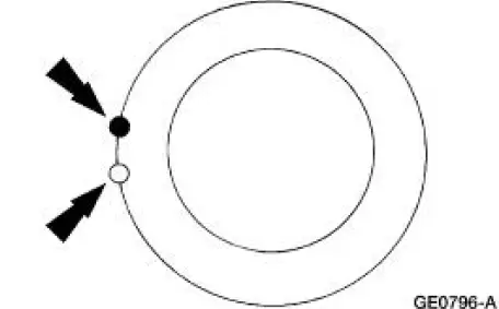
3. Inspect the driveshaft for signs of physical damage, missing balance weight, undercoating, incorrect seating, wear and binding universal joints. Clean the driveshaft and install new universal joints or a new driveshaft if damaged. Check the index marks (paint spots) on the rear of the driveshaft and pinion flange. If these marks are more than one-quarter turn apart, disconnect the driveshaft and re-index to align the marks as closely as possible. After any corrections are made, recheck for vibration at the road test speed. If the vibration is gone, reinstall the wheels and road test. If the vibration persists, proceed to Step 4.
4. Raise the vehicle on a hoist and remove the wheels. Rotate the driveshaft by turning the axle and measure the runout at the front, the center, and the rear of the driveshaft with the indicator.
If the runout exceeds 0.89 mm (0.035 inch) at the front or center, a new driveshaft must be installed. If the front and center are within this limit, but the rear runout is not, mark the rear runout high point and proceed to Step 5. If the runout is within the limits at all points, proceed to Step 7.
5. NOTE: Check the U-joints during re-indexing. If a U-joint feels stiff or gritty, install new U-joints.
Scribe alignment marks on the driveshaft and the pinion flange. Disconnect the driveshaft, rotate it one-half turn, and reconnect it. Circular pinion flanges can be turned in one-quarter increments to fine tune the runout condition. Check the runout at the rear of the driveshaft. If it is still over 0.89 mm (0.035 inch), mark the high point and proceed to Step 6. If the runout is no longer excessive, check for vibration at the road test speed. If vibration is still present, re-index the driveshaft slip yoke on the transmission output shaft one-half turn and road test the vehicle.
If the vibration persists, proceed to Step 7.
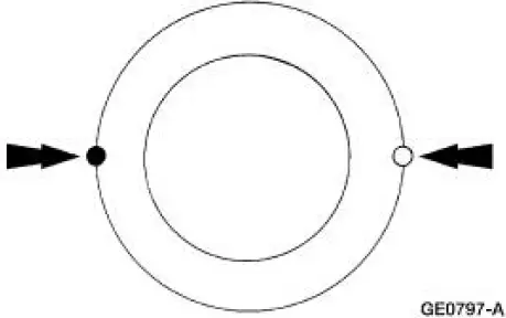
6. Excessive driveshaft runout may originate in the driveshaft itself or in the pinion flange. To determine which, compare the two high points marked in Steps 4 and 5. If the marks are close together, within about 25 mm (1 inch), a new shaft must be installed and the vehicle road tested.
If the marks are on opposite sides of the driveshaft, the yoke or pinion flange is responsible for the vibration.
When installing a new pinion flange, the driveshaft runout must not exceed 0.89 mm (0.035 inch).
When runout is within limits, recheck for vibration at road speed. If vibration persists, balance the driveshaft.
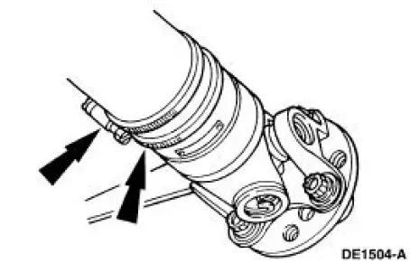
7. To balance the driveshaft, install one or two hose clamps on the driveshaft, near the rear.
Position of the hose clamp head(s) can be determined by trial-and-error.
8. Mark the rear of the driveshaft into four approximately equal sectors and number the marks 1 through 4. Install a hose clamp on the driveshaft with its head at position No. 1.
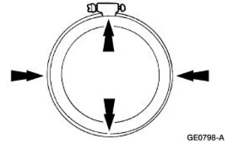
Check for vibration at road speed. Recheck with the clamp at each of the other positions to find the position that shows minimum vibration. If two adjacent positions show equal improvement, position the clamp head between them.
9. If the vibration persists, add a second clamp at the same position and recheck for vibration.
If no improvement is noted, rotate the clamps in opposite directions, equal distances from the best position determined in Step 8. Separate the clamp heads about 13 mm (1/2 inch) and recheck for vibration at the road speed.
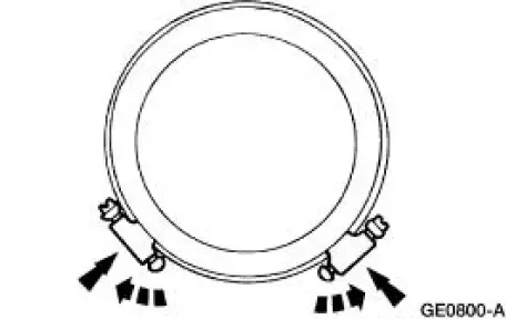
Repeat the process with increasing separation until the best combination is found or the vibration is reduced to an acceptable level.
10. Install the wheels and road test (vibration noticeable on the hoist may not be evident during the road test). If the vibration is still not acceptable, install a new axle driveline vibration damper first, if so equipped.
Driveshaft Vibrates
1. Road test the vehicle to determine the critical vibration points. Note the road speed, the engine RPM, and the shift lever positions at which the vibration occurs.
2. Stop the vehicle, place the transmission lever in neutral and run the engine through the critical speed ranges determined in Step 1.
3. If no vibration is felt, balance the driveshaft. Refer to Driveline Vibration in this section.
Traction-Lok Differential Operation Check
A Traction-Lok differential can be checked for correct operation without removing it from the rear axle housing.
WARNING: A vehicle equipped with a Traction-Lok differential will always have both wheels driving. If only one wheel is raised off the floor and the rear axle is driven by the engine, the wheel on the floor could drive the vehicle off the stand or jack. Be sure both rear wheels are off the floor.
With the engine off, raise only one rear wheel. Install the special tool on the wheel nuts.
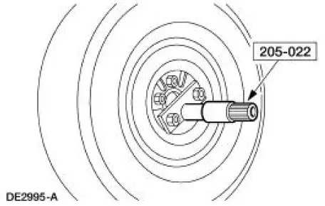
Use a torque wrench with a capacity of at least 271 Nm (200 lb-ft) to rotate the axle shaft. Be sure that the transmission is in NEUTRAL, and that one rear wheel is on the floor while the other rear wheel is raised off the floor. The breakaway torque required to start rotation must be at least 27 Nm (20 lb-ft).
The initial breakaway torque may be higher than the continuous turning torque.
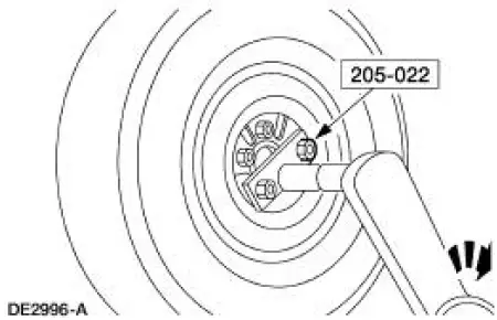
The axle shaft must turn with even pressure throughout the check without slipping or binding. If the torque reading is less than specified, check the differential case.
Traction-Lok Differential Check Road Test
1. Place one wheel on a dry surface and the other wheel on ice, mud or snow.
2. Gradually open the throttle to obtain maximum traction prior to break away. The ability to move the vehicle demonstrates correct operation of a Traction-Lok rear axle assembly.
3. When starting with one wheel on an excessively slippery surface, a slight application of the parking brake may be necessary to help energize the Traction-Lok feature of the differential.
Release the brake when traction is established. Use light throttle on starting to provide maximum traction.
4. If, with unequal traction, both wheels slip, the limited slip rear axle has done all it can possibly do.
5. In extreme cases of differences in traction, the wheel with the least traction may spin after the Traction-Lok has transferred as much torque as possible to the non-slipping wheel.
Companion Flange Runout Check
CAUTION: Pinion bearing preload must be reset if the pinion nut has been loosened or removed for pinion flange reindexing or installation.
1. Raise the vehicle on a twin-post hoist that supports the rear axle.
2. Remove the driveshaft.
3. Check the pinion flange for damage.
4. Position the Companion Flange Runout Gauge on the pinion flange.
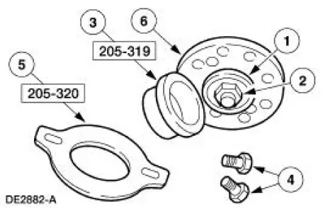
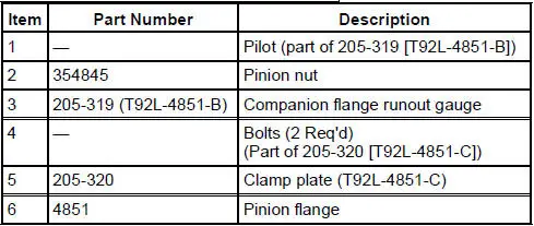
5. Position the special tools on the pinion flange.
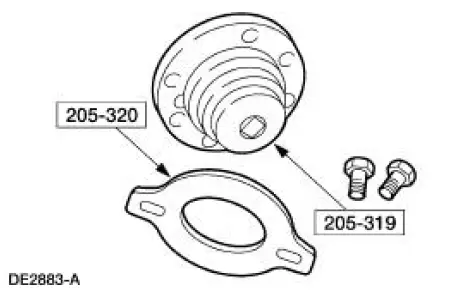
6. Align the holes on the clamp plate with the holes in the pinion flange and install the bolts. Snug the bolts evenly.
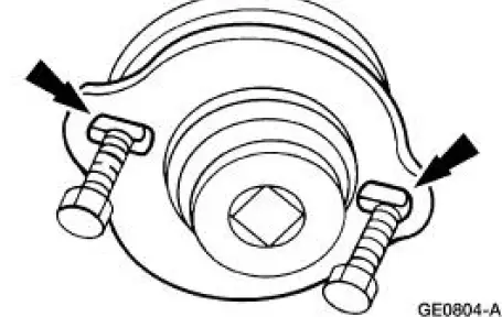
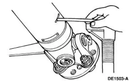
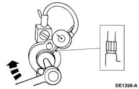
7. Position the special tool as shown. Turn the Companion Flange Runout Gauge, and locate and mark the high spot on the pinion flange with yellow paint.
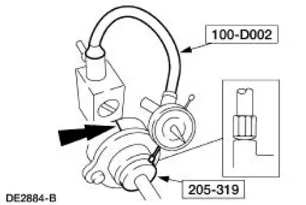
If the flange runout exceeds 0.25 mm (0.010 inch), remove the pinion flange, reindex the flange onehalf turn on the pinion, and reinstall it.
8. Check the runout again. If necessary, rotate the flange until an acceptable runout is obtained. If the flange runout is still more than 0.25 mm (0.010 inch), install a new pinion flange.
9. If excessive runout is still evident after installing a new pinion flange, install a new ring and pinion. Repeat the above checks until the runout is within specifications.
10. Install the driveshaft.
Tooth Contact Pattern Check - Gearset
1. To check the gear tooth contact, paint the gear teeth with the special marking compound. A mixture that is too wet will run and smear; a mixture that is too dry cannot be pressed out from between the teeth.
2. Use a box wrench on the ring gear bolts as a lever to rotate the ring gear several complete revolutions in both directions or until a clear tooth contact pattern is obtained.
3. Certain types of gear tooth contact patterns on the ring gear indicate incorrect adjustment.
Incorrect adjustment can be corrected by readjusting the ring gear or the pinion.
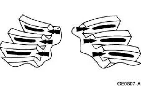
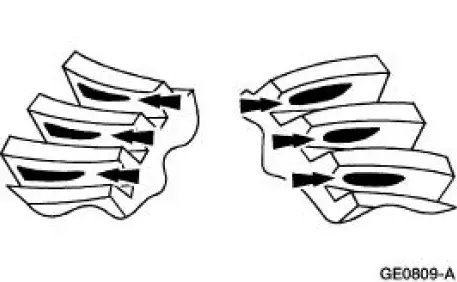
Contact Pattern Location
In general, desirable ring gear tooth patterns must have the following characteristics:
- drive pattern on the drive side ring gear well centered on the tooth
- coast pattern on the coast side ring gear well centered on the tooth
- clearance between the pattern and the top of the tooth
- no hard lines where the pressure is high
Acceptable ring gear tooth patterns for all axles.
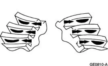
Correct backlash with a thinner pinion position shim required.
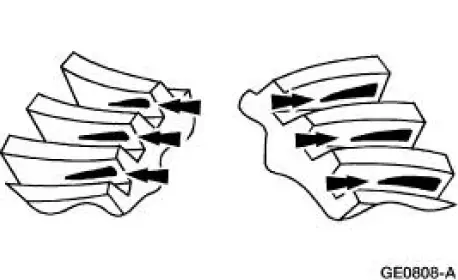
Correct backlash with a thicker pinion position shim required.
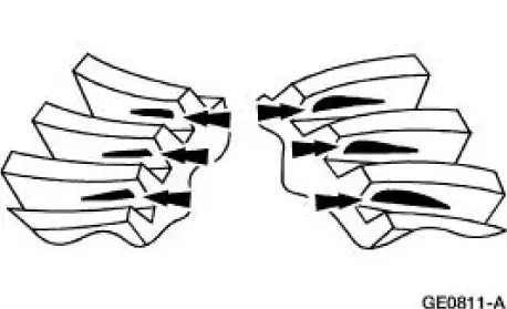
Correct pinion position shim that requires a decrease in backlash.
Correct pinion position shim that requires an increase in backlash.
 Symptom Chart
Condition
Possible Sources
Action
Traction-Lok
does not work in
snow, mud or on
ice
Differential.
CARRY OUT the Traction-
Lok Differenti ...
 Driveline Angle Inspection
Special Tool(s)
Anglemaster II Driveline
Inclinometer
164-R2402 or equivalent
NOTE: An incorrect driveline angle can cause a vibration or shudder.
1. Check the vehicle for evidence o ...
Other materials:
Handles, Locks, Latches and Mechanisms
General Specifications
Torque Specifications
LOCK REPAIR/REPLACEMENT SPECIFICATIONS
...
Camber Adjustment - Rear
1. Loosen the nut.
2. Rotate the bolt and the cam to the correct camber setting.
3. Tighten the nut while holding the bolt and the cam stationary.
4. Recheck the wheel alignment. Follow the manufacturer's instructions.
Adjust as necessary. ...
Spark Plugs
Special Tool(s)
Remover, Spark Plug Wire
303-106 (T74P-6666A)
Material
Item
Specification
Silicone Brake Caliper Grease
and Dielectric Compound
D7AZ-19A331-A or equivalent
ESE-M1C171-
A
Removal and Installation
CAUTION: ...
