Ford Mustang (1999-2004) Service Manual: Driveshaft (Removal and Installation)
Material
| Item | Specification |
| Threadlock and Sealer E0AZ-19554-AA | WSK-M2G351-A5 (type II) |
Removal and Installation
1. Raise and support the vehicle.
2. Carry out the following:
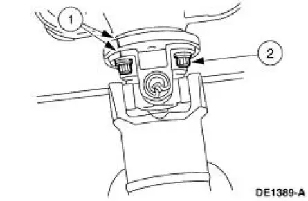
1. Place an index mark on the rear axle pinion flange and the driveshaft centering socket yoke.
2. Remove the four bolts.
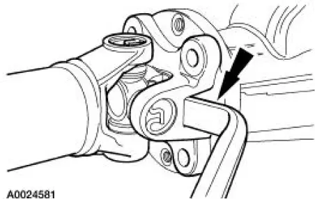
3. CAUTION: The driveshaft centering socket yoke fits tightly on the rear axle pinion flange pilot. Never hammer on the driveshaft or any of its components to disconnect the yoke from the flange. Pry only in the area shown, with a suitable tool, to disconnect the yoke from the flange.
Using a suitable tool as shown, disconnect the driveshaft centering socket yoke from the rear axle pinion flange.
4. CAUTION: Do not allow the slip yoke to bottom on the transmission output shaft.
Lower the rear end of the driveshaft to clear the rear axle housing. Pull the driveshaft rearward until the driveshaft slip yoke clears the transmission extension housing.
- Place a paint index mark on the driveshaft slip yoke and the transmission output shaft.
- Place a commercially available plug in the extension housing to prevent fluid leakage.
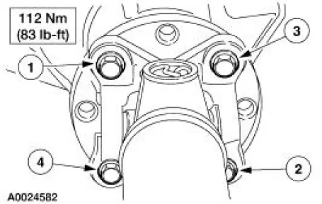
5. CAUTION: Install the driveshaft with new bolts. If new bolts are not available, apply threadlock and sealer to the threads of the original bolts.
CAUTION: Do not allow the slip yoke to bottom on the transmission output shaft.
CAUTION: The driveshaft centering socket yoke fits tightly on the rear axle pinion flange pilot. To make sure that the yoke seats squarely on the flange, tighten the bolts evenly in a cross pattern as shown.
NOTE: Clean all foreign material from the yoke areas of the driveshaft.
To install, reverse the removal procedure.
 Universal Joints
The universal joints are:
lubed-for-life design and require no lubrication.
equipped with nylon thrust washers, located at each base of the bearing
cup, which control end
play, position the need ...
 Driveshaft - Cobra
Material
Item
Specification
Threadlock and Sealer
E0AZ-19554-AA
WSK-M2G351-A5 (type
II)
Silicone Lubricant
(Aerosol)
F5AZ-19553-AA
ESR-M13P4-A
Removal and Installatio ...
Other materials:
Suspension System - General Information
Alignment Specifications
General Specifications
Torque Specifications
Description
Nm
lb-ft
Front suspension camber adjustment plate bolt
40
30
Front suspension camber adjustment plate nuts
40
30
Rear camber adjustment nut ...
Bearings - Inspection
NOTE: If any of the following conditions exist, install a new
bearing.
1. Inspect the bearing for a bent cage.
2. Inspect bearings for galling (metal smears on roller ends).
Galling is caused by overheating, poor lubrication or an overload
situatio ...
Disassembly
Initial disassembly
1. Remove the differential housing cover (4033) and drain the lubricant into
a suitable container.
2. Wipe the lubricant from the internal working parts and inspect the parts for
wear and damage.
3. Using the special tool, measure and n ...
