Ford Mustang (1999-2004) Service Manual: Electronic Leak Detection
Special Tool(s)
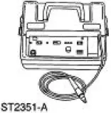 |
H10PM Refrigerant Leak Detector With Battery 216-00001 or equivalent |
CAUTION: Good ventilation is necessary in the area where electronic A/C leak testing is to be carried out. If the surrounding air is contaminated with refrigerant gas, the leak detector will indicate this gas all the time. Odors from other chemicals such as anti-freeze, diesel fuel, disc brake cleaner, or other cleaning solvents can cause the same problem. A fan, even in a wellventilated area, is very helpful in removing small traces of contamination from the air that might affect the leak detector.
1. NOTE: The system pressure should be between 413-551 kPa (60-80 psi) at 24C (75F) with the engine off.
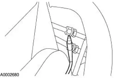
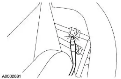
Leak test the refrigerant system using the Refrigerant Leak Detector. Follow the instructions included with the leak detector for handling and operation techniques.
2. If a leak is found, discharge and recover the refrigerant. For additional information, refer to Air Conditioning (A/C) System Recovery, Evacuation and Charging in this section.
- Repair the system.
- Test the system for normal operation.
 Manifold Gauge Set Connection
Special Tool(s)
R-134a Manifold Gauge Set
176-R032A or equivalent
1. Turn both valves on the R-134a Manifold Gauge Set clockwise to close the
low- and highpressure
hoses to the center ...
 Tracer Dye Leak Detection
Special Tool(s)
120 Watt 110 Volt UV Lamp
20C
164-R0721 or equivalent
NOTE: Ford Motor Company vehicles are produced with a permanent leak
tracer dye incorporated into
the A/C syste ...
Other materials:
Module Configuration
Module Configuration (Diagnosis and Testing)
Special Tool(s)
Worldwide Diagnostic System
(WDS)
418-F224
New Generation STAR (NGS)
Tester
418-F052 or equivalent
diagnostic tool
Principles of Operation
Some modules must be programme ...
Removal
1. Remove the center instrument panel register.
2. Remove the screws.
3. Disconnect the connectors.
4. Using the special tool, disconnect the temperature control cable from the
control head.
5. Remove the nuts and disconnect the vacuum connector.
...
Body Closures
General Specifications
Torque Specifications
Body Closures
The body closures consist of the following components:
door checks
front door
front door latch strikers
front door hinges
front door opening weatherstrips
hood
hood (Cobra) ...
