Ford Mustang (1999-2004) Service Manual: Climate Control System - General Information
General Specifications
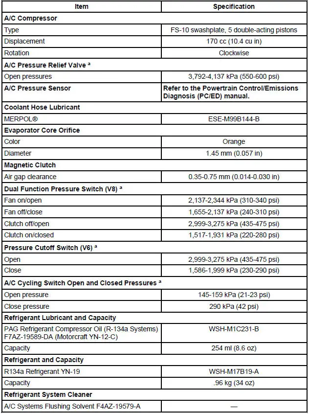
a - Manifold gauge set pressures may vary slightly depending on the distance between the service gauge port valve and the A/C pressure relief valve, the A/C cycling switch, the pressure cutoff switch (V6), and the dual function pressure switch (V8) location.
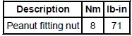
Torque Specifications
- Climate Control System (Description and Operation)
- Climate Control System (Diagnosis and Testing)
- Air Conditioning (A/C) System Check - Retail Procedure
- Spring Lock Coupling
- Heater Hose Coupling
- Air Conditioning Line (Peanut) Fitting
- Refrigerant System Tests
- Manifold Gauge Set Connection
- Electronic Leak Detection
- Tracer Dye Leak Detection
- Air Conditioning (A/C) System Flushing
- Air Conditioning (A/C) System Recovery, Evacuation and Charging
- Refrigerant System Filtering Following Air Conditioning (A/C) Component Installation
- Refrigerant Oil Adding
- Inspection and Assembly Requirements - Following an A/C Compressor Failure
- Refrigerant Identification Testing
- Contaminated Refrigerant Handling
- Vacuum Hose Repair - Mini-Tube

 Climate Control System (Description and Operation)
WARNING: To avoid accidental deployment and possible injury, the air
bag system
backup power supply must be depleted before repairing any climate control
components. To
deplete the backup power supp ...
Other materials:
Leakage Inspection
CAUTION: Do not try to stop the fluid leak by increasing the torque
beyond specifications.
This may cause damage to the case threads.
Check the fluid filler tube connection at the transmission case. If
leakage is found here, install a new
grommet.
Ch ...
Installation
CAUTION: The upper suspension arm and bushing nuts must be tightened
with the
suspension at curb height. Failure to do so can result in bushing failure,
resulting in poor ride
and handling.
NOTE: If installing a new upper suspension arm and bushing, mark the ...
Inspection and Verification
NOTE: A new instrument cluster must be reconfigured.
NOTE: The instrument panel dimmer switch is a part of the headlamp
switch.
1. Verify the customer concern.
2. Visually inspect for obvious signs of electrical damage.
Visual Inspection Chart
Electric ...
