Ford Mustang (1999-2004) Service Manual: Engine Dynamic Balance Shaft
Removal
1. Remove the timing chain (6268). For additional information, refer to Timing Chain in this section.
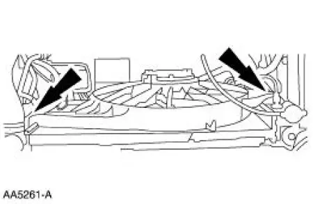
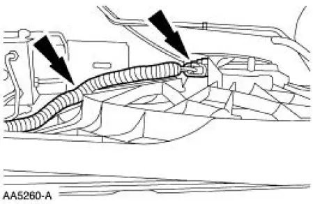
2. Disconnect and position the wire harness aside.
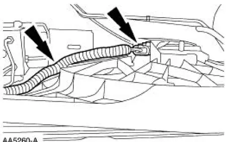
3. Remove the radiator fan and shroud assembly (8146).
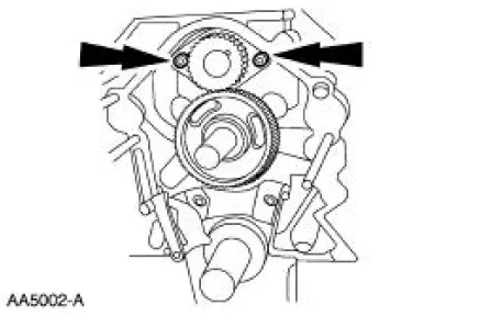
4. Remove the engine dynamic balance shaft (6A311).
- Remove the bolts.
- Remove the balance shaft driver gear, thrust plate and engine dynamic balance shaft as an assembly.
Installation
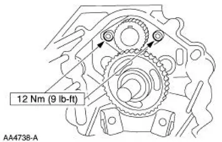
1. Turn the camshaft so that the timing mark is at 12 o'clock and install the engine dynamic balance shaft assembly into the cylinder block (6010). Turn the engine balance shaft driven gear so that the timing mark lines up with the timing mark on the engine balance shaft drive gear (6A303).
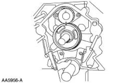
2. NOTE: If correctly aligned, the engine dynamic balance shaft keyway will be at 12 o'clock and the camshaft keyway will be at 6 o'clock on the camshaft.
Install the bolts.
3. Install the radiator fan and shroud assembly.
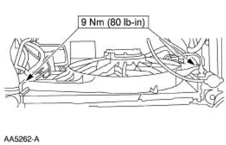
4. Connect the connector and install the pin-type retainer.
5. Install the timing chain. For additional information, refer to Timing Chain in this section.
 Camshaft
Material
Removal
1. Remove the valve tappets. For additional information, refer to Valve
Tappets in this section.
2. Remove the timing chain. For additional information, refer to Timing
Chain ...
 Timing Chain
Removal
1. Remove the timing cover. For additional information, refer to Engine
Front Cover in this section.
2. Remove the camshaft position sensor drive gear.
1. Remove the bolt.
2. Remov ...
Other materials:
Module - Passive Anti-Theft Transceiver
Removal
1. CAUTION: Electronic modules are sensitive to electrical
charges. If exposed to
these charges, damage may result.
Disconnect the battery ground cable (14301).
2. Remove the ignition switch lock cylinder (11582).
1. Insert the ignit ...
Shock Absorber
Removal
WARNING: All vehicles are equipped with gas pressurized shock absorbers
which will
extend unassisted. Do not apply heat or flame to the shock absorbers during
removal or
component servicing. Failure to follow these instructions can result in personal ...
Parking, Rear and License Lamps
Refer to Wiring Diagrams Cell 92 , Exterior for schematic and connector
information.
Special Tool(s)
73 III Automotive Meter or
equivalent
105-R0057
Inspection and Verification
1. Verify the customer concern by operating the parking lamps ...
