Ford Mustang (1999-2004) Service Manual: Engine (Installation)
Special Tool(s)
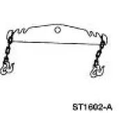 |
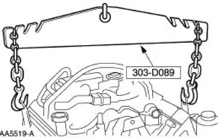
Spreader Bar 303-D089 (D93P-6001-A3) |
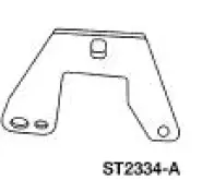 |
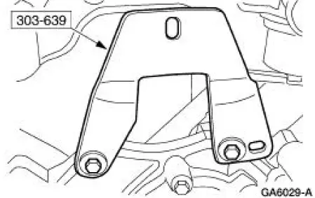
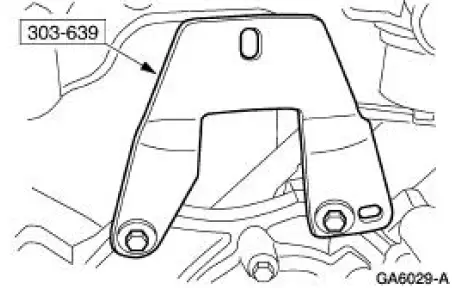
Support Bracket, Engine 303-639 |
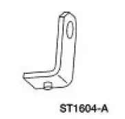 |
Lifting Bracket, Engine 303-D087 (D93P-6001-A1) |
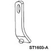 |
Lifting Bracket, Engine 303-D088 (D93P-6001-A2) |
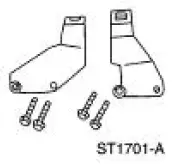 |
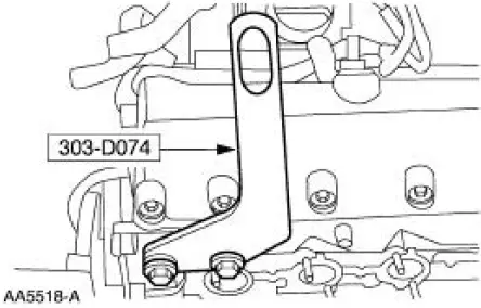
Lifting Bracket Set, Engine 303-D074 (D91P-6001-A) |
Material
| Item | Specification |
| Metal Surface Cleaner F4AZ-19A536-RA or equivalent | WSE-M5B392- A |
| Silicone Gasket and Sealant F7AZ-19554-EA or equivalent | WSE-M4G323- A4 |
| Super Premium SAE 5W-20 Engine Oil XO-5W20-QSP or equivalent | WSS-M2C153- H |
| Premium Engine Coolant E2FZ-19549-AA (In Canada CXC-10; In Oregon F5FZ- 19549-CC) or equivalent | ESE-M97B44- A |
1. NOTE: Adjust the transmission support jack as necessary to aid in the installation of the engine.
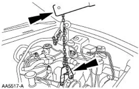
Using the special tool, install the engine.
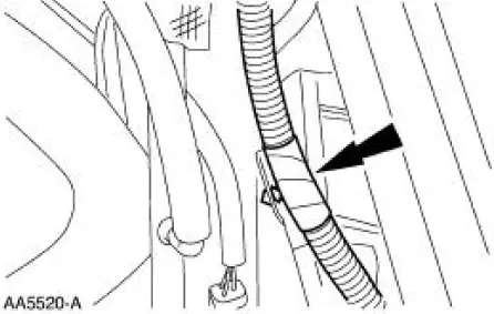
2. Connect the transmission wiring to the bracket during installation.
3. Remove the special tool.
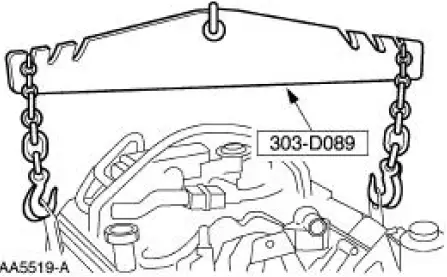
4. Install the special tool.
5. NOTE: This step will allow the installation of the exhaust manifold through the bottom and access for the removal of the engine lift brackets.
Using a suitable floor crane raise the engine.
6. Remove the RH and LH special tool.
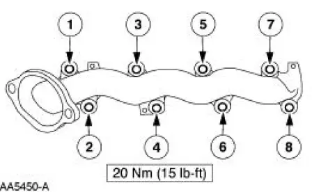
7. Install new gaskets and the exhaust manifolds, tighten the nuts in the sequence shown.
8. Lower the engine, remove the special tool.
9. Install the generator. For additional information, refer to Section.
10. Raise the vehicle. for additional information, refer to Section.
11. Install the power steering pump. For additional information, refer to Section.
12. Install the bolt and the body ground.
13. Install the nine bell housing bolts.
14. Install the starter. For additional information, refer to Section.
15. NOTE: This will need to be done as the H-pipe is being positioned.
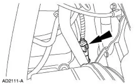
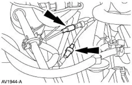
Connect the LH heated oxygen sensor.
16. NOTE: This will need to be done as the H-pipe is being positioned.
Connect the RH heated oxygen sensor.
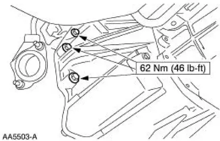
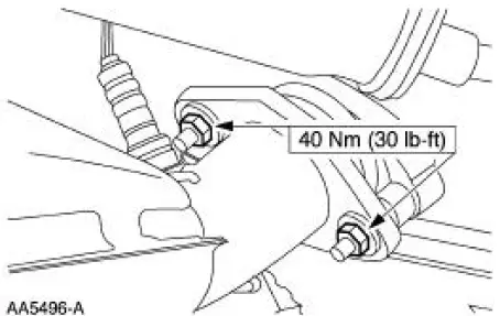
17. Re-position the H-pipe and install the four exhaust flange to manifold nuts.
18. Lower the vehicle.
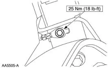
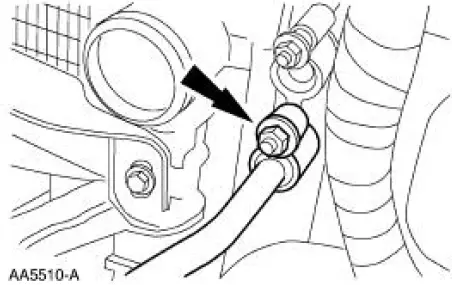
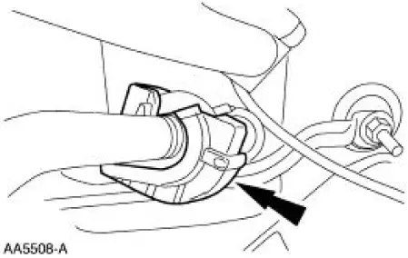
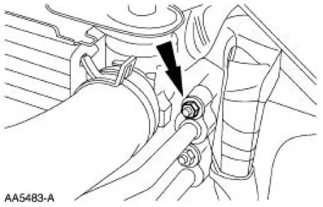
19. NOTE: The O-ring seal must be inspected and cleaned before installation. For additional information, refer to Section.
Install the A/C line and tighten the nut.
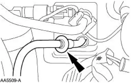
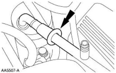
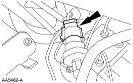
20. NOTE: The O-ring seal must be inspected and cleaned before installation. For additional information, refer to Section.
Connect the line to the evaporator core.
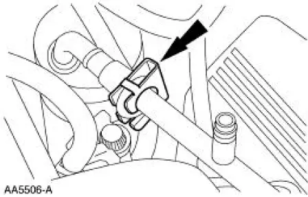
21. Install the safety clip.
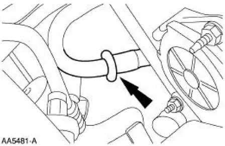
22. NOTE: The O-ring seal must be inspected and cleaned before installation. For additional information, refer to Section.
Connect the line to the receiver drier.
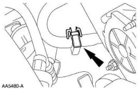
23. Install the safety clip.
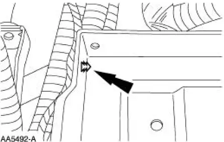
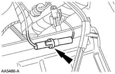
24. Connect the degas sensor lead to the battery tray.
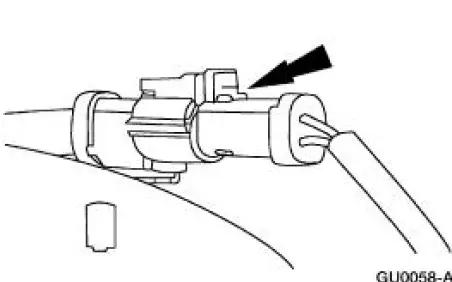
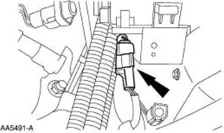
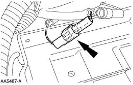
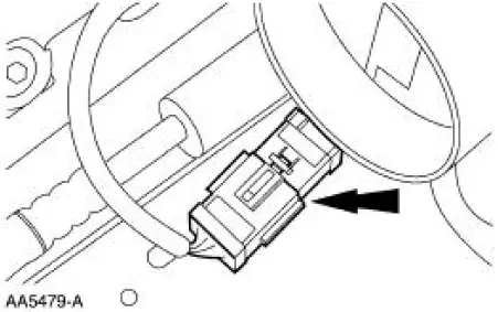
25. Connect the connector.
26. Install the battery leads.
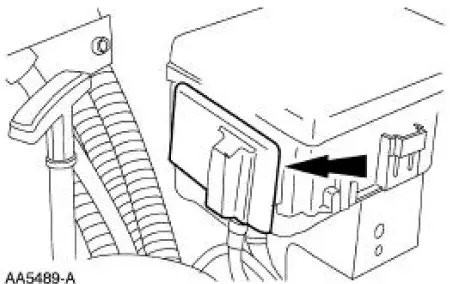
27. Position the access cover.
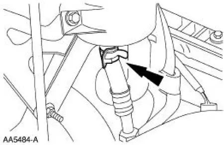
28. Connect the ground connector
29. Connect the connector.
30. Connect the fuse link.
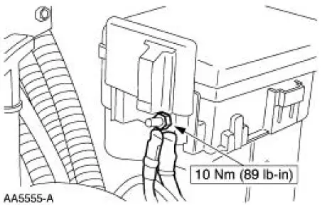
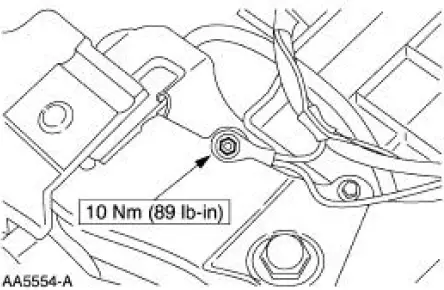
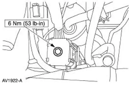
31. Install and tighten the body ground.
32. Connect the power steering line.
33. NOTE: The O-ring seal must be inspected and cleaned before installation. For additional information, refer to Section.
Install the A/C line.
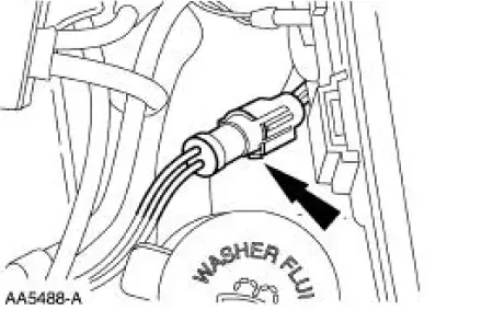
34. Connect the A/C pressure cycle switch.
35. NOTE: The O-ring seal must be inspected and cleaned before installation. For additional information, refer to Section.
Connect the A/C manifold suction line.
36. Install the safety clip to the manifold suction line.
37. Connect the electrical connector.
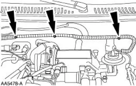
38. Connect the harness in three locations.
39. Connect the engine bulkhead connector.
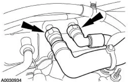
40. Connect the heater water hoses.
41. Connect the climate control vacuum supply lines.
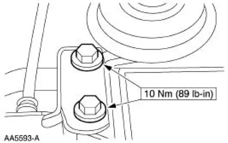
42. Position the cables and install the bracket.
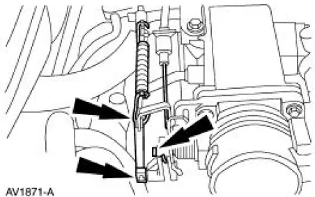
43. Connect the throttle cable, speed control actuator cable and the return spring.
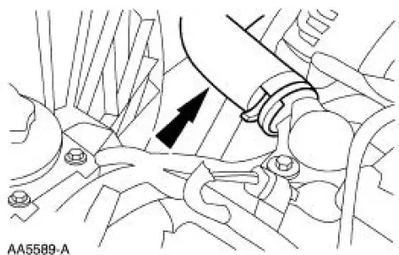
44. Connect the upper radiator hose from the water outlet adapter.
45. Connect the fuel lines. For additional information, refer to Section.
46. Install the battery. For additional information, refer to Section.
47. Install the air cleaner and outlet tube. For additional information, refer to Section.
48. Install the degas bottle.
49. Fill the fluids to the correct levels.
50. Start the engine and check for leaks. Stop the engine and recheck the fluid levels.
51. Recharge the A/C system. For additional information, refer to Section.
52. Install the hood.
 Cylinder Heads (Installation)
Special Tool(s)
Installer, Crankshaft Vibration
Damper
303-102 (T74P-6316-B)
Installer, Front Cover Oil Seal
303-335 (T88T-6701-A)
Holding Tool, Crankshaft
3 ...
Other materials:
Stay Pad - Convertible Top
Removal
1. Remove the convertible top material. For additional information, refer to
Convertible Top
Material in this section.
2. Remove the rear window glass. For additional information, refer to
Convertible Top Assembly-
Rear Window Glass in this section. ...
Bezel
Removal
1. Remove the shifter top control panel.
2. Disconnect the electrical connectors.
3. Remove the shifter bezel.
4. Remove the bulb from the bezel.
5. Disconnect the connector.
6. CAUTION: Extra force may be needed to lift up on the handle. Do not ...
Air Conditioning (A/C) Pressure Relief Valve - 4.6L
Material
Item
Specification
PAG Refrigerant Compressor
Oil (R-134a Systems)
F7AZ-19589-DA (Motorcraft YN-
12-C)
WSH-M1C231-
B
Removal and Installation
NOTE: Installation of a new suction accumulator is not required when
repairing the ...
