Ford Mustang (1999-2004) Service Manual: Cylinder Heads (Installation)
Special Tool(s)
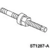 |
Installer, Crankshaft Vibration Damper 303-102 (T74P-6316-B) |
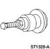 |
Installer, Front Cover Oil Seal 303-335 (T88T-6701-A) |
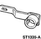 |
Holding Tool, Crankshaft 303-448 (T93P-6303-A) |
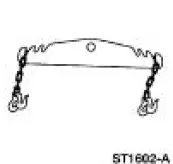 |
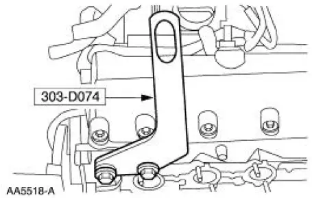
Spreader Bar 303-D089 (D93P-6001-A3) |
 |
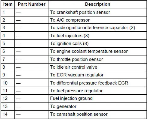
Lifting Bracket Set, Engine 303-D074 (D91P-6001-A) |
 |
Strap Wrench 303-D055 (D85L-6000-A) or equivalent |
 |
Compressor, Valve Spring 303-567 (T97P-6565-AH) |
 |
Compressor Spacer, Valve Spring 303-382 (T91P-6565-AH) |
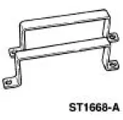 |
Remover/Installer, Cylinder Head 303-572 (T97T-6000-A) |
Material
| Item | Specification |
| Motorcraft Silicone Gasket Remover ZC-30 | - |
| Motorcraft Metal Surface Prep ZC-31 | - |
| Hydraulic Chain Tensioner Retaining Clip 1L3Z-6P250-AA | - |
| Silicone Gasket and Sealant F7AZ-19554-EA or equivalent | WSE-M4G323- A4 |
| Super Premium SAE 5W-20 Engine Oil XO-5W20-QSP or equivalent | WSS-M2C153- H |
Both cylinder heads
1. CAUTION: The gasket sealing surfaces on the cylinder head and cylinder block must be clean. For additional information, refer to Cylinder Heads in the Removal portion of this section.
CAUTION: The use of sealing aids (aviation cement, copper spray and glue) is not permitted. The gasket must be installed dry.
CAUTION: The new gasket has a film coating which is crucial to the gasket's ability to seal correctly. Do not scratch the gasket.
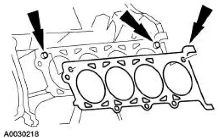
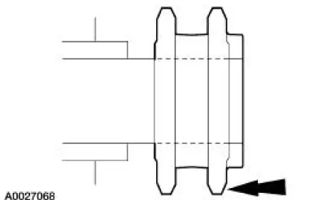
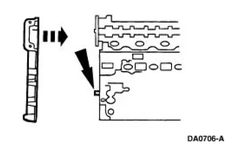
NOTE: RH head gasket shown; LH head gasket similar.
Install the head gasket over the dowel pins.
2. CAUTION: Cylinder head machining or milling is not authorized by the Ford Motor Company. Cylinder head flatness must be within 0.0254 mm (0.001 in) across a 38.1 mm (1.5 in) square area.
CAUTION: The use of sealing aids (aviation cement, copper spray and glue) is not permitted. The gasket must be installed dry.
CAUTION: Do not allow the dowels to scratch the sealing surface of the cylinder head during cylinder head installation.
NOTE: The new cylinder head bolts must be lightly oiled with a rag, and allowed to drain for a few minutes prior to installation.
NOTE: RH head gasket shown; LH head gasket similar.
Install the cylinder head on the dowels and the head gasket. Loosely install new bolts.
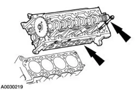
NOTE: Position the cylinder head(s) over the dowels on the head gasket(s).
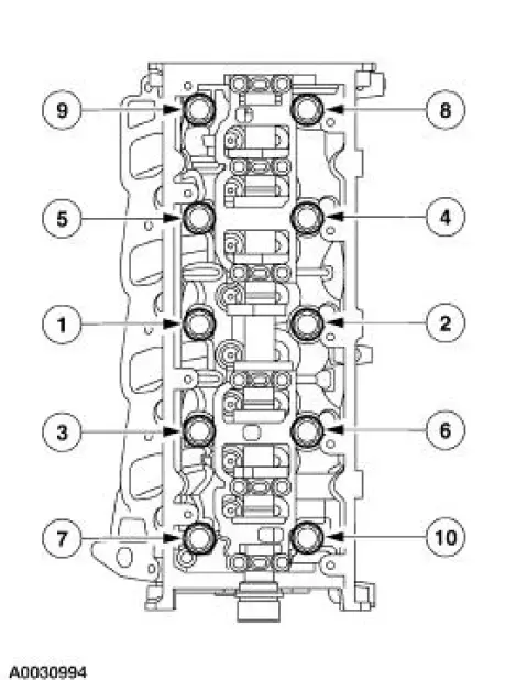
3. NOTE: LH shown, RH similar.
Tighten the bolts in six stages in the sequence shown.
- Stage 1: Tighten to 40 Nm (30 lb-ft).
- Stage 2: Tighten an additional 90 degrees.
- Stage 3: Loosen the bolts a minimum of one full turn.
- Stage 4: Tighten to 40 Nm (30 lb-ft).
- Stage 5: Tighten an additional 90 degrees.
- Stage 6: Tighten an additional 90 degrees.
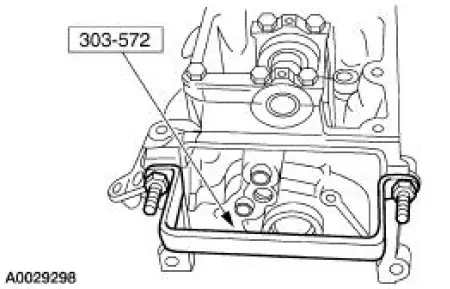
4. Remove the special tools from both ends of the cylinder head.
NOTE: Lubricate the hydraulic lash adjusters with clean engine oil.
5. Install the hydraulic lash adjusters in their original locations.
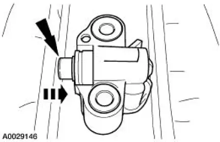
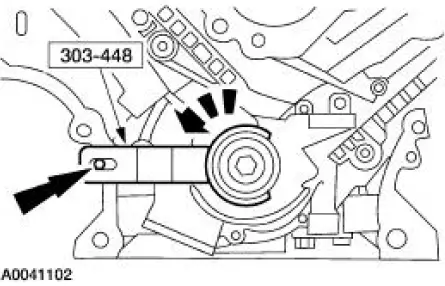
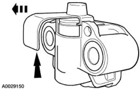
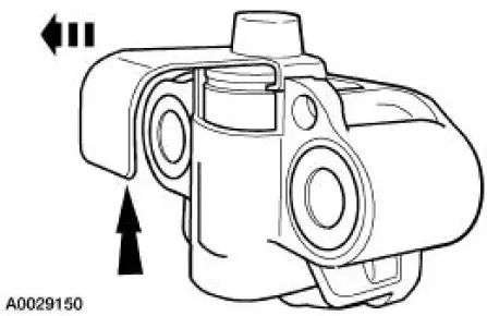
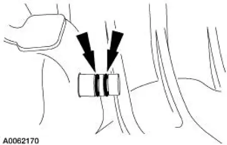
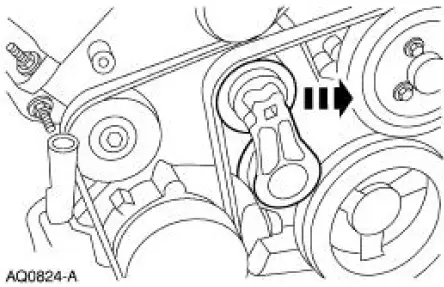
6. CAUTION: Timing chain procedures must be followed exactly or damage to the valves and pistons will result.
NOTE: LH shown, RH similar.
Compress each tensioner plunger, using a vise.
7. Install a retaining clip on each tensioner to hold the plunger in during installation
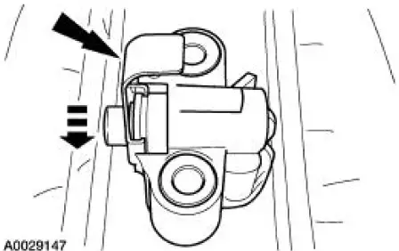
8. Remove the tensioner from the vise.
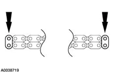
9. If the copper links are not visible, mark one link on one end and one link on the other end, and use as timing marks.
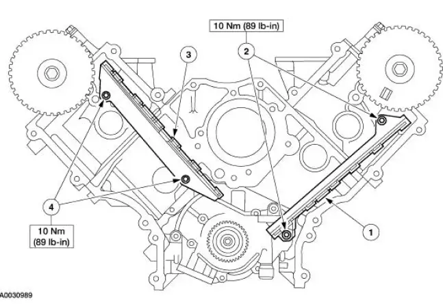
10. Install the timing chain guides.
1. Position LH timing chain guide.
2. Install and tighten the bolts.
3. Position the RH timing chain guide.
4. Install and tighten the RH bolts.
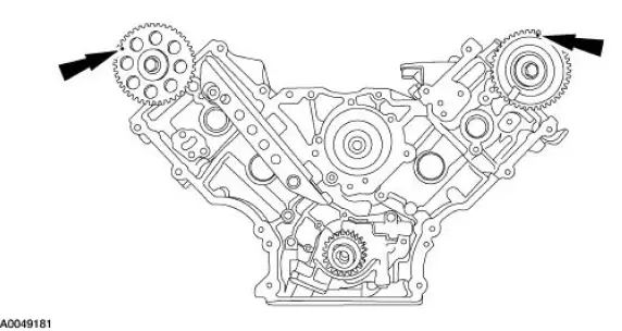
11. Rotate the RH camshaft sprocket until the timing mark is approximately at the 11 o'clock position. Rotate the LH camshaft sprocket until the timing mark is approximately at the 12 o'clock position.
12. CAUTION: When instructed to do so, rotate the crankshaft counterclockwise only.
Do not rotate past the position shown or severe piston and valve damage can occur.
NOTE: The number one cylinder is at top dead center (TDC) when the stud on the engine block fits into the slot in the handle of the special tool.
Using the special tool, position the crankshaft so the number one cylinder is at TDC.
13. Remove the special tool.
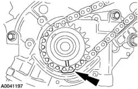
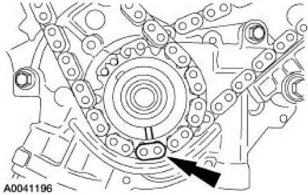
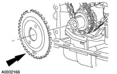
14. Install the crankshaft sprocket, making sure the flange faces forward.
15. Position the LH (inner) timing chain on the crankshaft sprocket, aligning the copper (marked) link with the timing mark on the sprocket.
16. Install the LH timing chain on the camshaft sprocket, aligning the copper (marked) link with the timing marks on the sprocket.
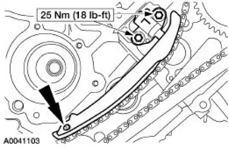
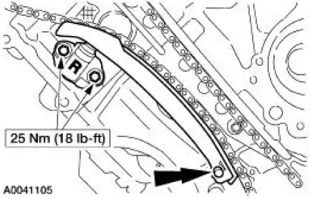
17. NOTE: The LH timing chain tensioner arm has a bump near the dowel hole for identification.
Position the LH timing chain tensioner arm on the dowel pin and install the LH timing chain tensioner.
18. Remove the retaining clip from the LH timing chain tensioner.
19. Position the RH (outer) timing chain on the crankshaft sprocket, aligning the copper (marked) link with the timing mark on the sprocket.
20. Install the RH timing chain on the camshaft sprocket, aligning the copper (marked) link with the timing marks on the sprocket.
21. Position the RH timing chain tensioner arm on the dowel pin and install the RH timing chain tensioner.
22. Remove the retaining clip from the RH timing chain tensioner.
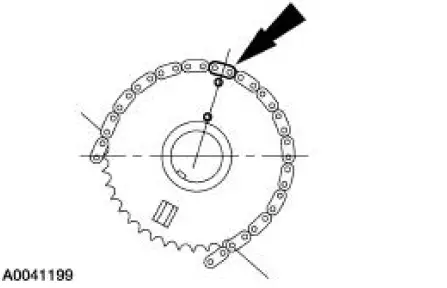
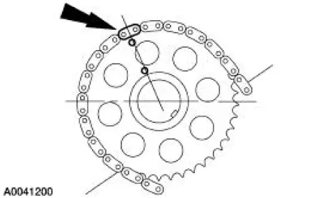
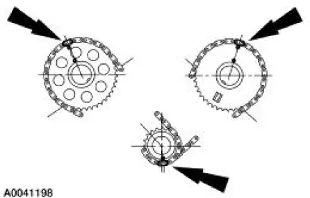
23. Make sure that the copper (marked) chain links are lined up with the dots on the crankshaft sprockets and the camshaft sprocket.
24. Install the crankshaft sensor ring on the crankshaft.
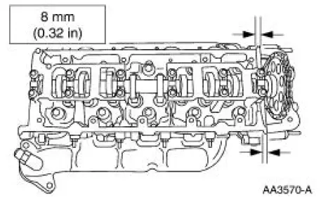
25. NOTE: If the engine front cover is not secured within four minutes, the sealant must be removed and the sealing area cleaned with metal surface cleaner. Allow to dry until there is no sign of wetness or four minutes, whichever is longer. Failure to follow this procedure can cause future oil leakage.
Apply a bead of sealant along the head-to-block surface as shown.
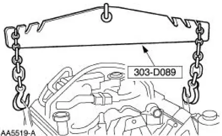
26. Install a new engine front cover gasket on the engine front cover. Position the engine front cover. Install the fasteners finger-tight.
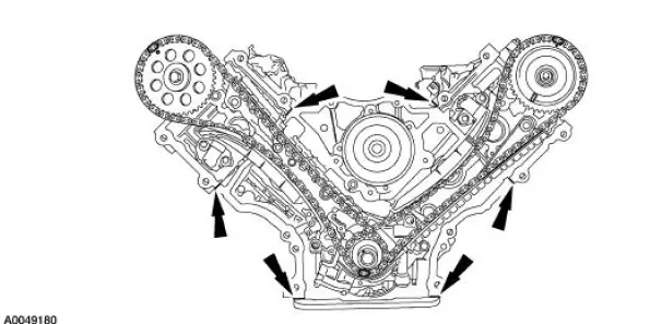
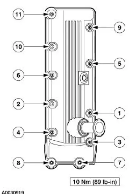
27. Tighten the front cover fasteners in the sequence shown.
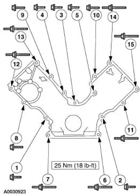

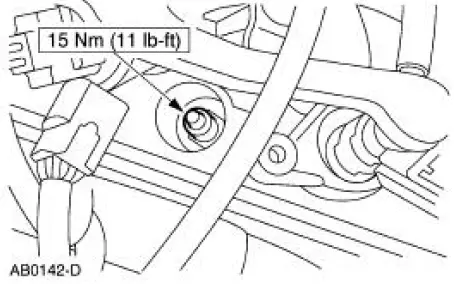
28. Loosely install the bolts, then tighten the bolts in three stages in the sequence shown.
- Stage 1: Tighten to 2 Nm (18 lb-in).
- Stage 2: Tighten to 20 Nm (15 lb-ft).
- Stage 3: Tighten an additional 60 degrees
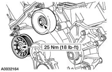
29. Install the belt idler pulleys.
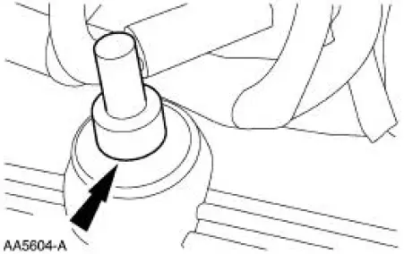
30. Lubricate the engine front cover and the front oil seal inner lip with clean engine oil.
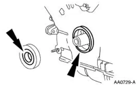
31. Using the special tool, install the front oil seal.
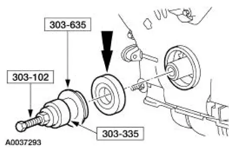
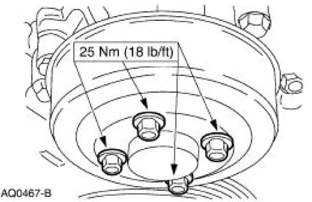
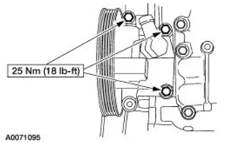
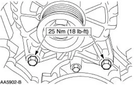
32. Install the coolant pump pulley and bolts.
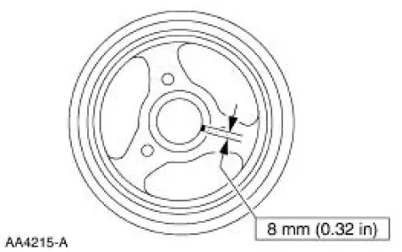
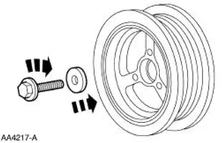
33. NOTE: The crankshaft pulley must be installed within four minutes of applying the sealant.
Apply silicone gasket and sealant to the Woodruff key slot on the crankshaft pulley.
34. Using the special tool, install the crankshaft pulley.
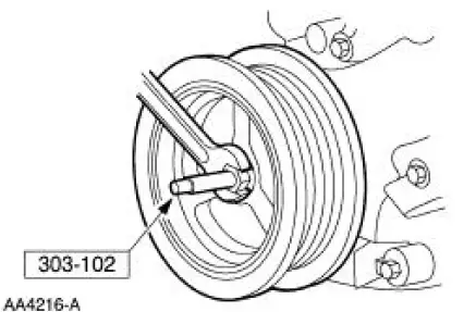
35. NOTE: Use special tool 303-009 or a suitable strap wrench to hold the crankshaft pulley.
Install the washer and the bolt. Tighten the bolt in four stages.
- Stage 1: Tighten to 90 Nm (66 lb-ft).
- Stage 2: Loosen one full turn.
- Stage 3: Tighten to 50 Nm (37 lb-ft).
- Stage 4: Tighten an additional 90 degrees.
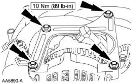
36. Install the RH engine mount.
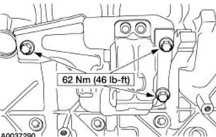
37. NOTE: Only three bolts are required for installation.
Install the power steering pump bolts.
- Position the power steering pump.
- Install the bolts.
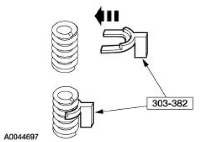
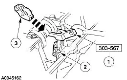
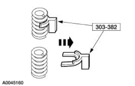
38. Install the special tool between the valve spring coils to prevent valve stem seal damage.
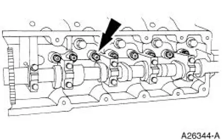
39. NOTE: Lubricate the camshaft roller followers using clean engine oil.
NOTE: Position the cam lobe away from the camshaft roller follower location prior to installing each camshaft roller follower.
Install the camshaft roller followers.
1. Install the special tool.
2. Compress the valve spring.
3. Install the camshaft roller followers in their original locations.
40. Remove the special tool.
41. NOTE: One spark plug shown, others similar.
Install the spark plugs.
42. NOTE: RH side shown, LH side similar.
NOTE: If not secured within four minutes, the sealant must be removed and the sealing area cleaned. To clean the sealing area, use silicone gasket remover and metal surface prep. Follow the directions on the packaging. Failure to follow this procedure can cause future oil leakage.
Apply silicone gasket and sealant in the locations shown.
43. NOTE: RH valve cover shown, LH similar.
Install the valve covers.
LH cylinder head
44. NOTE: Lubricate the O-ring seal with clean engine oil.
Install a new O-ring.
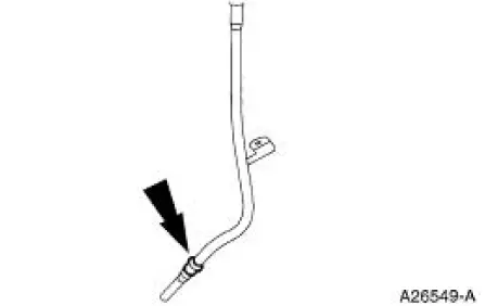
45. Install the oil level indicator tube.
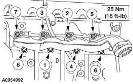
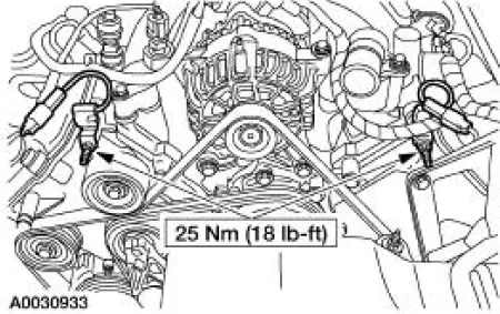
46. Install the LH exhaust manifold.
- Install a new manifold gasket.
- Install the LH exhaust manifold.
- Tighten the nuts in the sequence shown.
47. Connect the lower end of the exhaust gas recirculation (EGR) tube to the LH exhaust manifold.
RH cylinder head
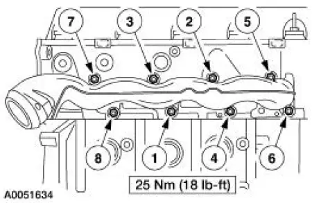
48. Install the RH exhaust manifold.
- Install a new exhaust manifold gasket.
- Install the RH exhaust manifold.
- Tighten the nuts in the sequence shown.
Both cylinder heads
49. Inspect O-ring seals and install new O-ring seals as necessary.
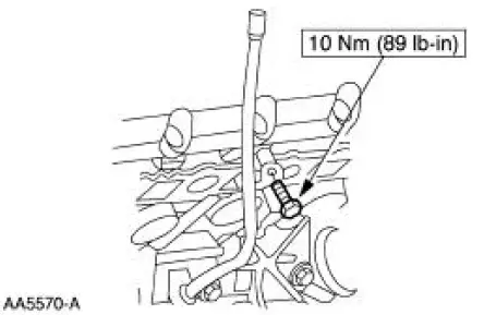
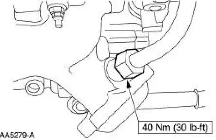
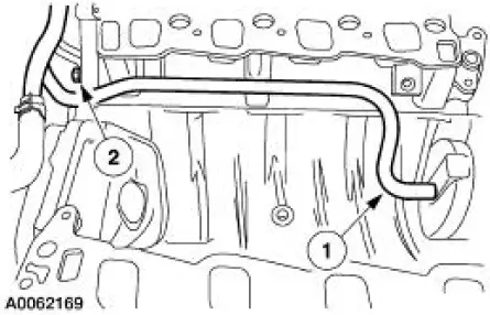
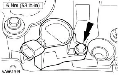
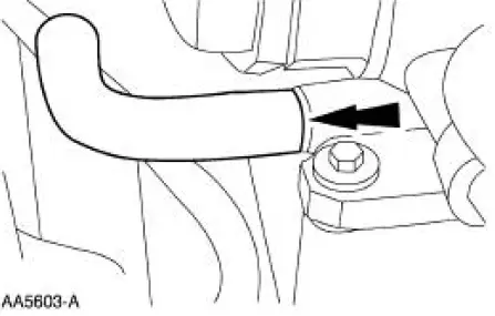
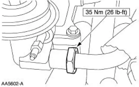
50. Install the coolant bypass tube.
1. Install the bypass tube.
2. Install the nut.
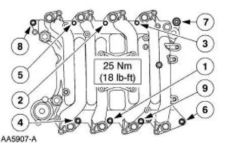
51. Install the intake manifold and gaskets. Tighten the bolts in the sequence shown.
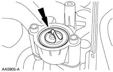
52. Install the thermostat and O-ring.
- Install a new O-ring as necessary.
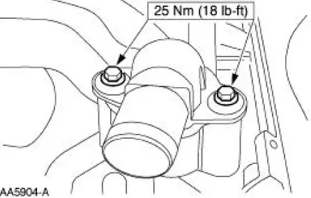
53. Install the coolant outlet adapter.
54. Install the bolts and the generator.
55. Install the upper generator support bracket.
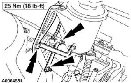
56. Position the power steering reservoir and bracket, then install the bolts.
57. Install the accessory drive belt.
58. Install the radio interference capacitors.
59. Install the ignition coils and bolts.
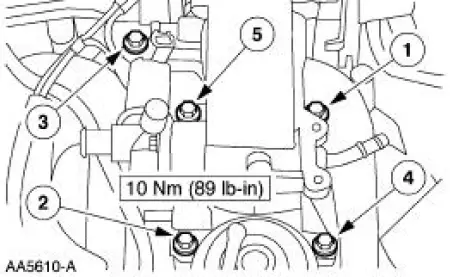
60. Position the throttle body and install the bolts, tightening in the sequence shown.
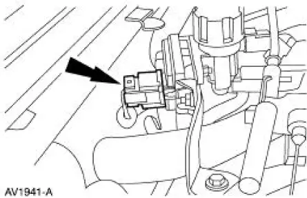
61. Connect the vacuum line to the fuel pressure sensor.
62. Install the positive crankcase ventilation (PCV) valve and hose as an assembly.
63. Connect the PCV hose to the base of the throttle body.
64. Connect the EGR tube to the EGR valve.
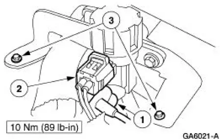
65. Install the EGR vacuum regulator solenoid.
1. Install the vacuum lines.
2. Install the electrical connector.
3. Install the bolts.
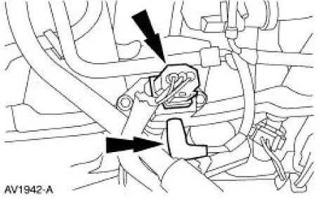
66. Connect the hoses from the differential pressure feedback EGR transducer.
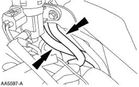
67. Connect the differential pressure feedback EGR electrical connector.
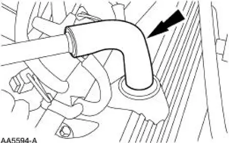
68. Install the breather tube.
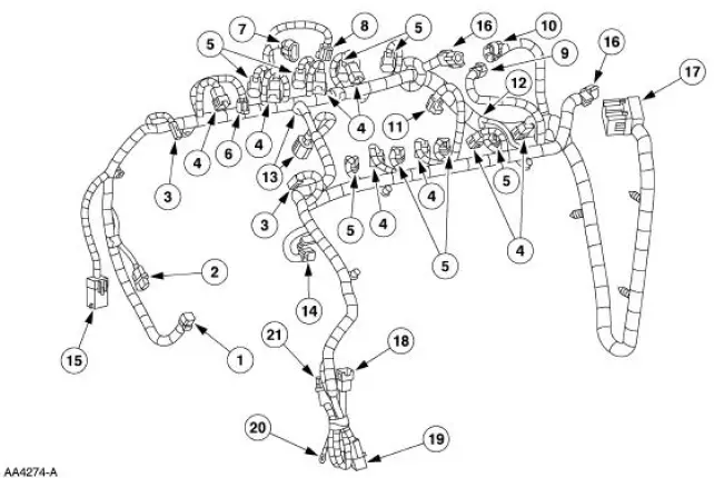
69. Install the engine control sensor wiring.

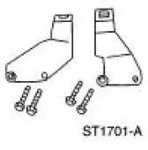
70. Install the RH and LH special tool
71. Using the special tool, remove the engine from the stand.
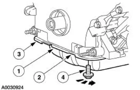
72. Install the separator plate.
73. Install the flywheel.
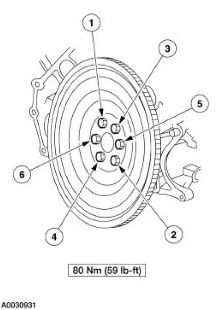
74. Install the engine. For additional information, refer to Engine in the Installation portion of this section.
 Engine (Assembly)
Special Tool(s)
Guides, Connecting Rod
303-442 (T93P-6136-A)
Installer, Crankshaft Rear Oil
Seal
303-518 (T95P-6701-DH)
Installer, Crankshaft Rear Oil
Seal
...
 Engine (Installation)
Special Tool(s)
Spreader Bar
303-D089 (D93P-6001-A3)
Support Bracket, Engine
303-639
Lifting Bracket, Engine
303-D087 (D93P-6001-A1)
Lifting Bracke ...
Other materials:
Battery and Cables
Vehicles are equipped with a 12 volt maintenance-free battery that
contains a built-in hydrometer. The
hydrometer eye indication is as follows:
A green dot means the battery is OK.
A yellow dot, red dot, or when the green dot is not visible,
...
Removal
1. Disconnect the battery ground cable. For additional information, refer to
Section.
2. Drain the cooling system. For additional information, refer to Section.
3. Recover the refrigerant. For additional information, refer to Section.
4. Remove the air cle ...
Gearshift Rail and Fork
Disassembly and Assembly
1. Disassemble the first/second and third/fourth shift rail as follows:
Rotate the interlock plate until it is opposite of the shift links.
Slide off the third/fourth shift fork and shift link. Separate the link
from the ...
