Ford Mustang (1999-2004) Service Manual: Exhaust Gas Recirculation (EGR) Valve - Cobra
Removal and Installation
1. Disconnect the accelerator cable and the speed control cable.
2. Remove the accelerator cable bracket bolts.
3. Release the clip and position the accelerator cable bracket and the cables aside.
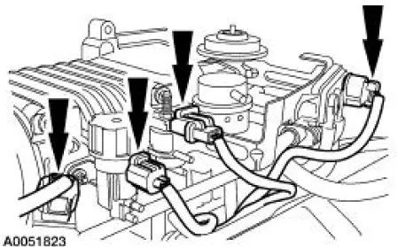
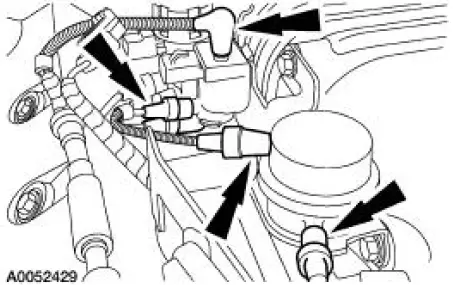
4. Disconnect the electrical connectors from the fuel pulse damper, EGR vacuum regulator solenoid, supercharger bypass vacuum solenoid, and the differential pressure feedback EGR system.
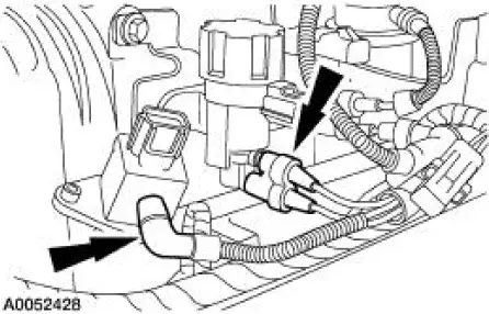
5. Disconnect the vacuum hoses from the differential pressure feedback EGR system.
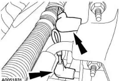
6. Disconnect the vacuum hoses from the supercharger bypass vacuum solenoid, and the actuator.
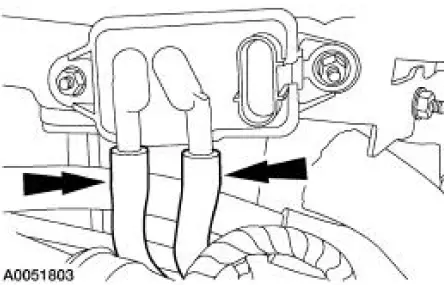
7. Disconnect the vacuum hoses from the fuel pulse damper and the EGR vacuum regulator solenoid.
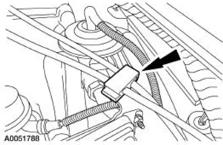
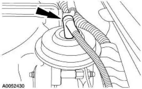
8. Disconnect the vacuum hose from the EGR valve.
9. Disconnect the vacuum hoses at the back of the supercharger and position the vacuum harness aside.
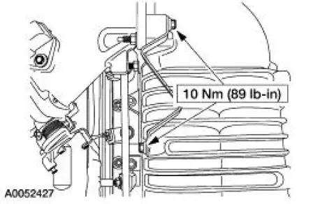
10. Remove the vacuum accessory bracket mounting nut.
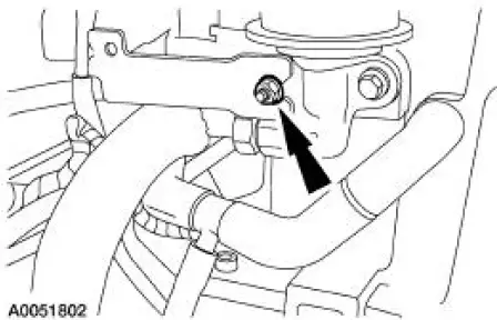
11. Remove the mounting bolts, and the vacuum accessory bracket.
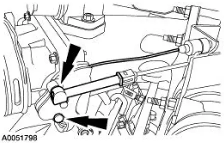
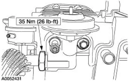
12. Disconnect the exhaust manifold to EGR valve tube.
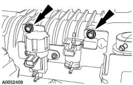
13. NOTE: Discard the EGR valve gasket.
Remove the mounting bolts and the EGR valve.
14. NOTE: Install a new EGR valve gasket.
To install, reverse the removal procedure.
 Exhaust Gas Recirculation (EGR) Valve
Removal and Installation
NOTE: The 4.6L, 2V is shown. The 3.8L is similar.
1. Disconnect the vacuum hose.
2. Disconnect the EGR tube from the EGR valve.
3. Remove the two bolts, the EGR valve an ...
 Exhaust Gas Recirculation (EGR) Valve - Mach I
Removal and Installation
1. Remove the air intake scoop. For additional information, refer to
Section.
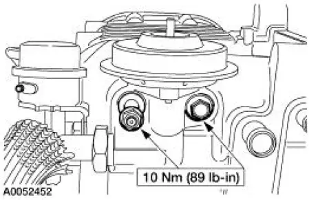
2. Remove the exhaust gas recirculation (EGR) valve.
1. Disconnect the EGR tube upper fi ...
Other materials:
Information contained on the tire sidewall
Both U.S. and Canada Federal regulations require tire manufacturers
to place standardized information on the sidewall of all tires. This
information identifies and describes the fundamental characteristics of
the tire and also provides a U.S. DOT Tire Identifi ...
Suction Accumulator
NOTE: Installation of a new suction accumulator is not required when
repairing the air conditioning
system except when there is physical evidence of contamination from a failed A/C
compressor or
damage to the suction accumulator.
In addition to th ...
Installation
1. Clean the A/C disc and field coil and pulley mounting surfaces.
2. CAUTION: Do not use air tools. The A/C clutch field coil can be easily
damaged.
Install the A/C clutch field coil.
1. Place the A/C clutch field coil on the A/C compressor with the A/C
...
