Ford Mustang (1999-2004) Service Manual: Flywheel Ring Gear
Removal
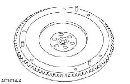
1. Remove the flywheel.
2. WARNING: This procedure should be carried out only by a correctly equipped and experienced acetylene torch operator. Tongs must be used or asbestos gloves worn when handling the heated flywheel ring gear. Failure to follow these instructions can result in personal injury.
CAUTION: Tap the flywheel ring gear evenly to prevent binding.
Remove the flywheel ring gear from the flywheel.
- Evenly heat the flywheel ring gear with an acetylene torch and use a brass drift to drive the flywheel ring gear off the flywheel.
Installation
1. WARNING: This procedure should be carried out only by a properly equipped and experienced acetylene torch operator. Tongs must be used or asbestos gloves worn when handling the heated flywheel ring gear. Failure to follow these instructions can result in personal injury.
CAUTION: Do not heat the flywheel ring gear beyond 261C (500F). Use heatindicating crayons to prevent overheating.
CAUTION: Keep the torch moving to prevent hot spots.
Evenly heat the flywheel ring gear with an acetylene torch.
- Install the flywheel ring gear with the bevel on the flywheel ring gear facing the rear of the flywheel.
- Use a brass drift to tap the flywheel ring gear into position, reheat as necessary.
2. Install the flywheel.
 Pilot Bearing
Special Tool(s)
Puller with Slide Hammer
308-001 (T58L-101-B)
1. Remove the clutch disc and the clutch pressure plate. For additional
information, refer to Disc
and Pressure Plate-3.8 ...
 Clutch Controls
General Specifications
Torque Specifications
...
Other materials:
Rear Wheel Bearing and Axle Shaft Oil Seal
Special Tool(s)
Adapter for 303-224
205-153 (T80T-4000-W)
Installer, Axle Shaft Bearing
205-124 (T78P-1225-A)
Installer, Rear Axle Oil Seal
205-390 (T97T-1177-B)
Remover, Axle Bearing
205-219 (T85L-1225-AH)
S ...
System Flushing - CIII Power Steering Pump
WARNING: Do not mix oil types. Any mixture or any unapproved oil can
lead to seal
deterioration and leaks. A leak can ultimately cause loss of fluid, which can
result in a loss of
power steering assist.
1. Remove the fuel pump fuse from the battery junction ...
Checks and Services
Certain basic maintenance checks and inspections should be carried out at
specified intervals. Any
recognized adverse condition should be corrected as soon as possible.
Maximum Oil Change Interval (Normal Schedule)
8,000 km (5,000 miles) or 6 months, whiche ...
