Ford Mustang (1999-2004) Service Manual: Fuel Charging Wiring Harness
Removal and Installation
WARNING: Do not smoke or carry lighted tobacco or open flame of any type when working on or near any fuel related components. Highly flammable mixtures are always present and may ignite. Failure to follow these instructions may result in personal injury.
1. Disconnect the battery ground cable. For additional information, refer to Section.
2. Remove the upper intake manifold. For additional information, refer to Section.
3. Disconnect the following electrical connectors.
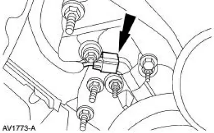
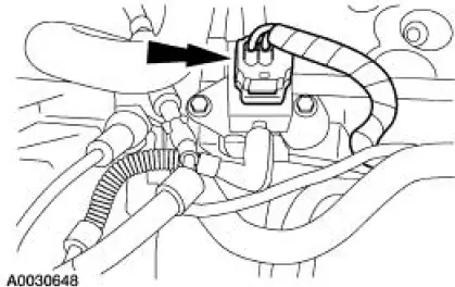
- 42-pin engine bulkhead connector
- 16-pin connector
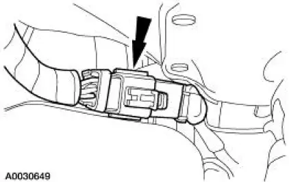
- 8-pin connector
- A/C pressure switch
4. Separate the wiring harness from the dash panel.
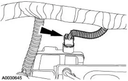
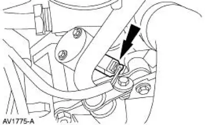
5. Disconnect the intake manifold runner control (IMRC) actuator electrical connector.
6. Disconnect the RH heated oxygen sensor (HO2S) electrical connector and the 16-pin electrical connector.
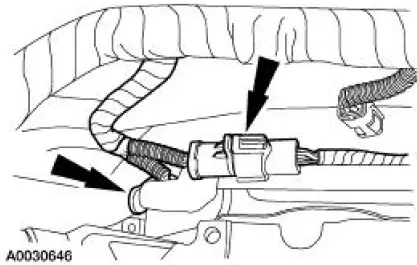
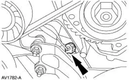
7. Disconnect the crankshaft position (CKP) sensor electrical connector.
8. Disconnect the camshaft position (CMP) sensor electrical connector.
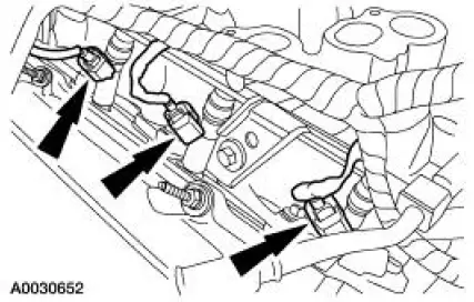
9. NOTE: Right side shown, left side similar.
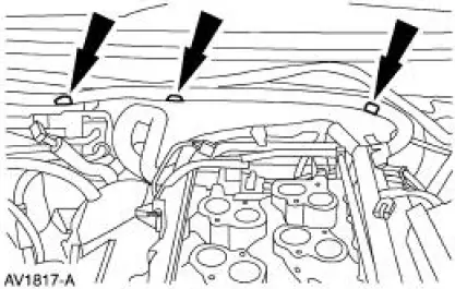
Disconnect the six fuel injector electrical connectors.
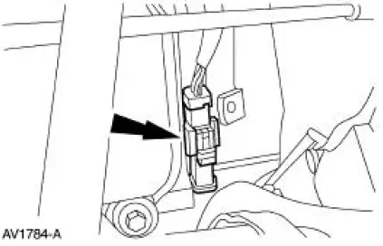
10. Disconnect the cylinder head temperature (CHT) sensor electrical connector on the back of the left cylinder head.
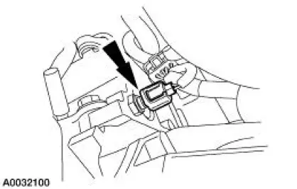
11. Disconnect the engine oil pressure sender electrical connector.
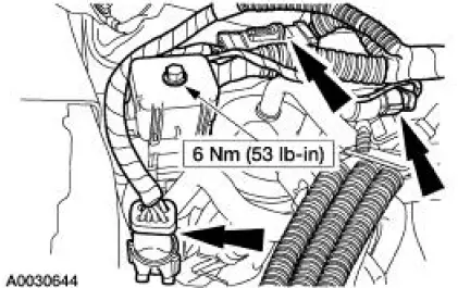
12. Disconnect the fuel pressure sensor electrical connector.
13. Disconnect the LH heated oxygen sensor (HO2S) electrical connector.
14. Disconnect the 16-pin electrical connector on the back of the left cylinder head.
15. Remove the wiring harness:
- Separate the wiring harness from the fuel supply manifold.
16. To install, reverse the removal procedure.
 Fuel Injectors
Material
Item
Specification
SAE 5W-20 Premium Synthetic
Blend Motor Oil
XO-5W20-QSP or equivalent
WSS-M2C153-
H
Removal and Installation
WARNING: Do not smoke or carry lighted ...
 Supply Manifold
Removal and Installation
WARNING: Do not smoke or carry lighted tobacco or open flame of any
type when
working on or near any fuel related components. Highly flammable mixtures are
always present
an ...
Other materials:
Torque Converter Cleaning And Inspection
Material
Item
Specification
MERCON V Automatic
Transmission Fluid
XT-5-QM, XT-5-DM
MERCON V
1. If a new torque converter is being installed, continue with Substep 2 of
Step 2.
2. If a new torque converter is not being installed, the fol ...
Oil Level Indicator and Tube
Removal and Installation
1. Remove the oil level indicator.
2. Remove the LH exhaust manifold. For additional information, refer to Exhaust
Manifold LH in
this section.
3. Remove the bolt.
4. Remove the oil level indicator tube.
5. To install, reverse t ...
Arm - Lower
Removal
CAUTION: Suspension fasteners are critical parts because they affect
performance of vital
components and systems and their failure can result in major service expense. A
new part with
the same part number or an equivalent part must be installed, if i ...
