Ford Mustang (1999-2004) Service Manual: Fuel Injection Supply Manifold and Fuel Injector
Material
| Item | Specification |
| SAE 5W-20 Premium Synthetic Blend Motor Oil XO-5W20-QSP | WSS-M2C153- H |
Removal and Installation
WARNING: Do not smoke or carry lighted tobacco or open flame of any type when working on or near any fuel related components. Highly flammable mixtures are always present and can ignite. Failure to follow these instructions can result in personal injury.
WARNING: Fuel in the fuel system remains under high pressure even when the engine is not running. Before working on or disconnecting any of the fuel lines or fuel system components, the fuel system pressure must be relieved. Failure to follow these instructions can result in personal injury.
1. Disconnect the battery ground cable.
2. Remove the air cleaner outlet tube. For additional information, refer to Section.
3. Release the fuel pressure. For additional information, refer to Section.
4. Disconnect the fuel supply hose spring lock coupling. For additional information, refer to Section.
5. Remove the exhaust gas recirculation (EGR) valve and the exhaust manifold-to-EGR valve tube. For additional information, refer to Section.
6. Remove the throttle body and spacer assembly.
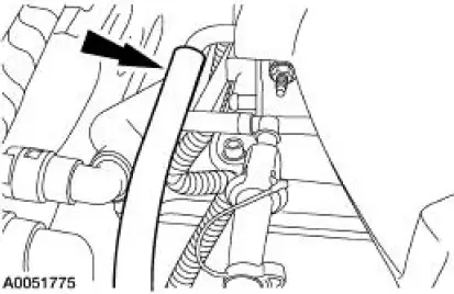
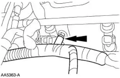
7. Disconnect the vacuum hose.
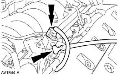
8. Disconnect the fuel pulse damper electrical connector and the vacuum hose.
9. NOTE: RH shown, LH similar.
Disconnect the eight fuel injector electrical connectors.
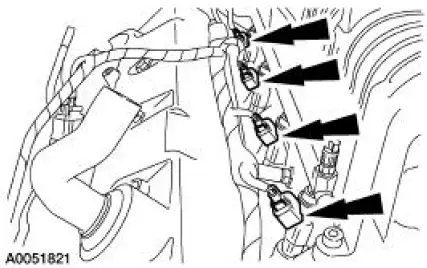
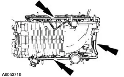
10. Separate the fuel charging wiring harness from the fuel injection supply manifold in four places.
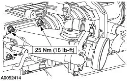
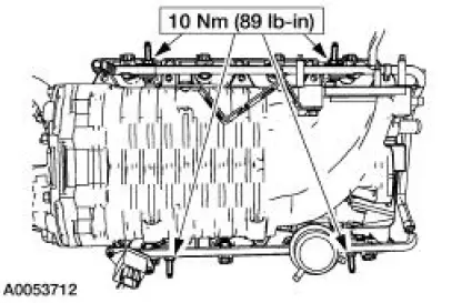
11. Remove the fuel supply manifold mounting studs.
12. Remove the fuel supply manifold and fuel injectors as an assembly.
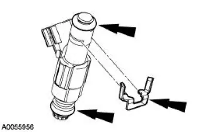
13. Remove the anti-rotation clips and the fuel injectors from the fuel supply manifold.
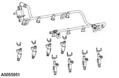
14. NOTE: Always install new O-rings.
NOTE: Lubricate the O-rings with clean engine oil to aid installation.
NOTE: Make sure the anti-rotation clips are installed.
To install, reverse the removal procedure.
 Fuel Charging Wiring Harness
Removal and Installation
WARNING: Do not smoke or carry lighted tobacco or open flame of any
type when
working on or near any fuel related components. Highly flammable mixtures are
always present
an ...
 Fuel Charging and Controls - Mach I 4.6L (4V)
General Specifications
Torque Specifications
...
Other materials:
Starting System (Description and Operation)
Starter Motor
The starter motor is a 12-volt unit that has the starter solenoid mounted on
the drive end housing and
functions as follows:
The current flows through the solenoid energizing coil until the
solenoid plunger is at the end of
its travel.
The ...
Extension Housing
Special Tool(s)
Installer, Bearing Cup
204-039 (T77F-1217-B)
Adapter for 303-224 (Handle)
205-153 (T80T-4000-W)
Disassembly and Assembly
1. Remove the bolt and the output shaft speed (OSS) sensor.
2. Remove the bolt a ...
Spark Plugs
Special Tool(s)
Remover, Spark Plug Wire
303-106 (T74P-6666A)
Material
Item
Specification
Silicone Brake Caliper Grease
and Dielectric Compound
D7AZ-19A331-A or equivalent
ESE-M1C171-
A
Removal and Installation
CAUTION: ...
