Ford Mustang (1999-2004) Service Manual: Headlamps
Refer to Wiring Diagrams Cell 85 , Headlamps for schematic and connector information.
Special Tool(s)
 |
73III Automotive Meter or equivalent 105-R0057 |
Inspection and Verification
1. Verify the customer concern by operating the headlamps.
2. Visually inspect for the following obvious signs of mechanical and electrical damage.
Visual Inspection Chart
| Mechanical | Electrical |
|
|
3. If the concern is not visually evident, determine the symptom and proceed to Symptom Chart.
Symptom Chart
| Condition | Possible Sources | Action |
|
|
|
|
|
|
|
|
|
|
|
|
|
|
|
|
|
|
|
|
|
Pinpoint Tests
PINPOINT TEST A: BOTH HEADLAMPS ARE INOPERATIVE
| Test Step | Result / Action to Take |
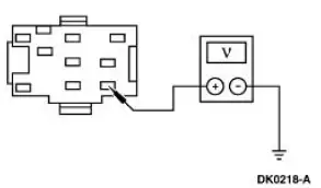
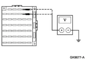
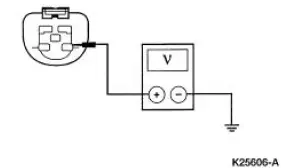
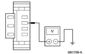
| A1 CHECK THE VOLTAGE TO THE HEADLAMP SWITCH | Yes GO to A2 . No REPAIR the circuit. TEST the system for normal operation. |
|
|
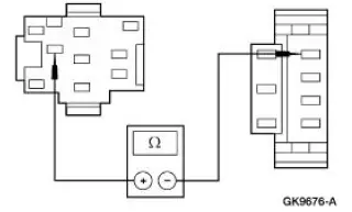
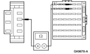
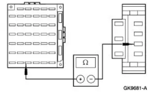
| A2 CHECK CIRCUIT 15 (RD/YE) FOR OPEN | Yes RECONNECT headlamp switch C205. GO to A3 . No REPAIR the circuit. TEST the system for normal operation. |
|
|
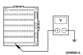
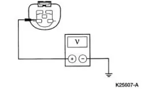
| A3 CHECK THE VOLTAGE TO THE MULTIFUNCTION SWITCH | Yes INSTALL a new multifunction switch; REFER to Section. TEST the system for normal operation. No INSTALL a new headlamp switch; REFER to Lamp Switch-Headlamp in this section. TEST the system for normal operation. |
|
PINPOINT TEST B: THE LOW BEAMS ARE INOPERATIVE
| Test Step | Result / Action to Take |
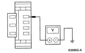
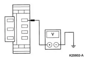
| B1 CHECK THE VOLTAGE TO CJB FUSE 4 (7.5A) AND CJB FUSE 10 (7.5A) | Yes Go To Pinpoint Test D . No GO to B2 . |
|
|
| B2 CHECK CIRCUIT 13 (RD/BK) FOR OPEN | Yes INSTALL a new multifunction switch; REFER to Section. TEST the system for normal operation. No REPAIR the circuit. TEST the system for normal operation. |
|
PINPOINT TEST C: THE HIGH BEAMS ARE INOPERATIVE
| Test Step | Result / Action to Take |
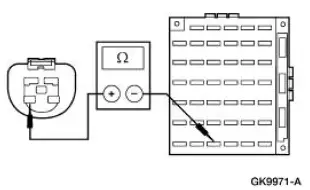
| C1 CHECK THE CIRCUIT 12 (LG/BK) | Yes RECONNECT the LH headlamp (13008). GO to C2 . No REPAIR the circuit. TEST the system for normal operation. |
|
|
| C2 CHECK THE VOLTAGE TO CJB FUSE 38 (20A) | Yes Go To Pinpoint Test E . No GO to C3 . |
|
|
| C3 CHECK CIRCUIT 632 (GY/OG) FOR OPEN | Yes INSTALL a new multifunction switch; REFER to Section. TEST the system for normal operation. No REPAIR the circuit. TEST the system for normal operation |
|
PINPOINT TEST D: ONE LOW BEAM HEADLAMP IS INOPERATIVE
| Test Step | Result / Action to Take |
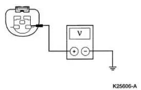
| D1 CHECK THE VOLTAGE TO THE INOPERATIVE HEADLAMP BULB | Yes INSTALL a new headlamp bulb; REFER to Bulb-Headlamp in this section. TEST the system for normal operation. No REPAIR the circuit. TEST the system for normal operation. |
|
PINPOINT TEST E: ONE HIGH BEAM HEADLAMP IS INOPERATIVE
| Test Step | Result / Action to Take |
| E1 CHECK THE VOLTAGE TO THE INOPERATIVE HEADLAMP BULB | Yes INSTALL a new headlamp bulb; REFER to Bulb- Headlamp in this section. TEST the system for normal operation. No REPAIR the circuit. TEST the system for normal operation. |
|
PINPOINT TEST F: THE HEADLAMPS ARE ON CONTINUOUSLY
| Test Step | Result / Action to Take |
| F1 CHECK THE HEADLAMP SWITCH | Yes GO to F2 . No INSTALL a new headlamp switch; REFER to Lamp Switch-Headlamp in this section. TEST the system for normal operation. |
|
|
| F2 CHECK THE MULTIFUNCTION SWITCH | Yes GO to F4 . No GO to F3 . |
|
|
| F3 CHECK CIRCUIT 15 (RD/YE) FOR SHORT TO POWER | Yes REPAIR the circuit. TEST the system for normal operation. No INSTALL a new multifunction switch; REFER to Section 211- 05 . TEST the system for normal operation. |
|
|
| F4 CHECK CIRCUIT 13 (RD/BK) FOR SHORT TO POWER | Yes REPAIR the circuit. TEST the system for normal operation. No GO to F5 . |
|
|
| F5 CHECK CIRCUIT 1056 (DB, LG) FOR VOLTAGE | Yes REPAIR Circuit 1056 (DB/LG). TEST the system for normal operations. No REPAIR Circuit 1055 (WH/LG). TEST the system for normal operations. |
|
 Exterior Lighting
Torque Specifications
Exterior Lighting
The exterior lighting system consists of the following components:
headlamps (13008)
parking lamps
rear lamps (13404)
high mounted stoplamp
...
 Stoplamps
Refer to Wiring Diagrams Cell 90 , Turn/Stop/Hazard Lamps for
schematic and connector information.
Special Tool(s)
73III Automotive Meter or
equivalent
105-R0057
Inspection and Ve ...
Other materials:
Wipers and Washers
General Specifications
Torque Specifications
Wipers and Washers
The wiper and washer system consists of the following components:
windshield wiper mounting arm and pivot shaft
pivot arms
windshield wiper blades
windshield washer reservoir
...
Lock Cylinder - Luggage Compartment Lid
Removal
1. NOTE: Individual lock cylinders are repaired by discarding the
inoperative cylinder and building
a new lock cylinder using the appropriate lock repair package. The lock
repair package includes
a detailed instruction sheet to build the ne ...
Changing a road wheel
WARNING: The use of tire sealants may damage your tire
pressure monitoring system and should not be used. However, if
you must use a sealant, have an authorized dealer install a new tire
pressure monitoring system sensor and valve stem.
WARNING: See Tire Press ...
