Ford Mustang (1999-2004) Service Manual: Stoplamps
Refer to Wiring Diagrams Cell 90 , Turn/Stop/Hazard Lamps for schematic and connector information.
Special Tool(s)
 |
73III Automotive Meter or equivalent 105-R0057 |
Inspection and Verification
1. Verify the customer concerns.
2. Visually inspect for the following obvious signs of mechanical or electrical damage.
Visual Inspection Chart
| Mechanical |
Electrical |
|
|
3. If an obvious cause for an observed or reported concern is found, correct the cause (if possible) before proceeding to the next step.
4. If the concern is not visually evident, determine the symptom and refer to the Symptom Chart.
Symptom Chart
| Condition | Possible Sources | Action |
|
|
|
|
|
|
|
|
|
Pinpoint Tests
PINPOINT TEST G: THE STOPLAMPS ARE INOPERATIVE
| Test Step | Result / Action to Take |
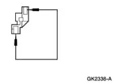
| G1 CHECK CIRCUIT 10 (LG/RD) FOR AN OPEN | Yes GO to G2 . No REPAIR the circuit. TEST the system for normal operation |
|
|
| G2 CHECK THE CIRCUIT 810 (RD/LG) FOR AN OPEN | Yes INSTALL a new BPP switch. REFER to Lamp Switch- Brake Pedal Position (BPP) in this section. TEST the system for normal operation. No REPAIR circuit 810 (RD/LG) or 569 (DG) as necessary. TEST the system for normal operation. |
|
PINPOINT TEST H: ONE OR MORE STOPLAMPS ARE INOPERATIVE
| Test Step | Result / Action to Take |
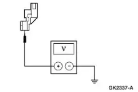
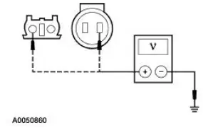
| H1 CHECK THE VOLTAGE TO THE INOPERATIVE STOPLAMP | Yes REPAIR circuit 1205 (BK). TEST the system for normal operation. No If high mounted stoplamp, REPAIR circuit 569 (DG). TEST the system for normal operation. If rear stoplamp, GO to H2 . |
|
|
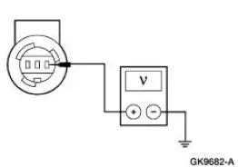
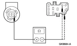
| H2 CHECK CIRCUIT 9 (LG/OG) OR 5 (OG/LB) FOR AN OPEN | Yes INSTALL a new multifunction switch. REFER to Section . TEST the system for normal operation. No REPAIR the circuit in question. TEST the system for normal operation. |
|
PINPOINT TEST I: THE STOPLAMPS ARE ON CONTINUOUSLY
| Test Step | Result / Action to Take |
| I1 CHECK THE BRAKE PEDAL POSITION (BPP) SWITCH | Yes GO to I2 . No INSTALL a new BPP switch. REFER to Lamp Switch- Brake Pedal Position (BPP) . TEST the system for normal operation. |
|
|
| I2 CHECK THE SPEED CONTROL SYSTEM | Yes GO to I3 . No REFER to Section. |
|
|
| I3 CHECK CIRCUIT 511 (LG) FOR SHORT TO POWER | Yes GO to I4 . No REPAIR the circuit. TEST the system for normal operation |
|
|
| I4 CHECK CIRCUIT 810 (LG/RD) FOR SHORT TO POWER | Yes GO to I5 . No REPAIR the circuit. TEST the system for normal operation |
|
|
| I5 CHECK THE MULTIFUNCTION SWITCH | Yes If the high mounted stoplamp is illuminated, REPAIR circuit 569 (DG) or 511 (LG) as necessary. TEST the system for normal operation. If only the LH stoplamp is illuminated, REPAIR circuit 9 (LG/OG). TEST the system for normal operation. If only the RH stoplamp is illuminated, REPAIR circuit 5 (OG/LB). TEST the system for normal operation. No INSTALL a new multifunction switch. REFER to Section. TEST the system for normal operation |
|
 Headlamps
Refer to Wiring Diagrams Cell 85 , Headlamps for schematic and
connector information.
Special Tool(s)
73III Automotive Meter or
equivalent
105-R0057
Inspection and Verification
...
 Turn Signal and Hazard Lamps
Refer to Wiring Diagrams Cell 90 , Turn/Stop/Hazard Lamps for schematic
and connector information.
Special Tool(s)
73 III Automotive Meter
105-R0057 or equivalent
Inspection and Ver ...
Other materials:
Engine
WARNING: Do not operate the engine with the hood open until the fan
blade has been first
examined for possible cracks and separation.
The 4.6L (4V) (281 CID) is a V-8 engine with the following features:
dual overhead camshafts
four valves per cylinder
s ...
Generator and Regulator
General Specifications
Torque Specifications
Generator
The charging system consists of the:
generator (GEN)
internal voltage regulator
The generator has an internal voltage regulator that is not installed
separately. The generator and
v ...
Installing child seats
Child Seats
Use a child safety seat (sometimes
called an infant carrier, convertible
seat, or toddler seat) for infants,
toddlers or children weighing
40 pounds (18 kilograms) or less
(generally age four or younger).
Using Lap and Shoulder Belts
WARNING: Airb ...
