Ford Mustang (1999-2004) Service Manual: Hinge Adjustment
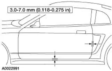
NOTE: The door should be adjusted for even and parallel fit with the body opening and surrounding panels as well as making sure that the anti-chuck pin is not binding on convertible models.
1. Remove the A-pillar lower trim panel.
2. Position the electrical connectors aside.
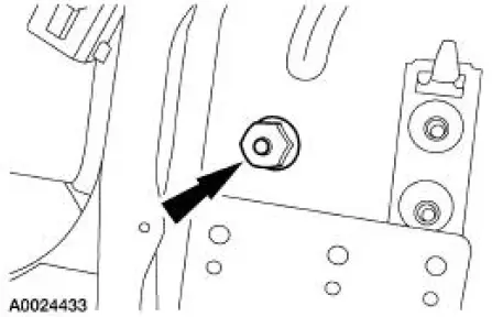
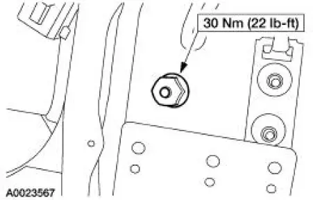
3. Loosen the lower front door hinge-to-body nut enough to permit movement.
4. Remove the fender. For additional information, refer to Section.
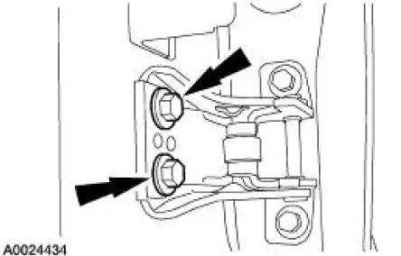
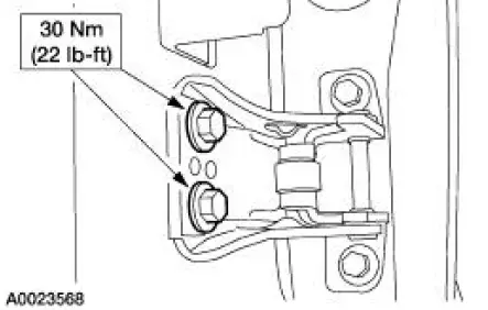
5. Mark the position of the upper and lower front door hinges to the body to use as reference points.
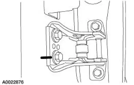
6. Loosen the four upper and lower front door hinge-to-body bolts enough to permit movement.
7. Adjust the front door to specification.
8. NOTE: After adjusting the door hinge, verify that the door can be closed easily and fits tightly.
Tighten the front door hinge to body bolts.
9. Tighten the front door hinge to body nut.
10. Install the electrical connectors.
11. Install the A-pillar lower trim panel.
12. Install the fender. For additional information, refer to Section.
 Body Closures
General Specifications
Torque Specifications
Body Closures
The body closures consist of the following components:
door checks
front door
front door latch strikers
front door hinges ...
 Door Alignment
NOTE: The door should be adjusted for even and parallel fit with the
body opening and surrounding
panels as well as making sure that the anti-chuck pin is not binding on
convertible models.
...
Other materials:
Assembly
1. CAUTION: Before beginning assembly, carry out and inspect the
following:
When building up subassemblies and assembling the transmission, ALWAYS use new
gaskets and seals.
All fasteners must be tightened to the torque specification indicated. In
addition ...
Installation
NOTE: Do not use a fiber disc to clean the surfaces. Fibers from
the disc can get into the oil pan and
oil and clog the oil bypass valve.
1. Clean and inspect the cylinder head for flatness.
2. Install a new head gasket on the cylinder block with the sm ...
Motor - Windshield Wiper
Removal
CAUTION: The internal permanent magnets used in the windshield
wiper motor are made
of a glass-like material. To avoid damaging the magnets, do not strike
the motor with a hammer
or any other object.
NOTE: The windshield wiper motor is n ...
