Ford Mustang (1999-2004) Service Manual: Ignition Switch Lock Cylinder - Non-Functional
Removal and Installation
1. NOTE: Make sure the front wheels are in the straight-ahead position.
Disconnect the battery ground cable (14301) and wait at least one minute to allow the depletion of the restraint system backup power supply.
2. WARNING: To avoid the risk of serious personal injury, read and follow all warnings, cautions, notes and instructions in the deactivation procedure.
Deactivate the supplemental restraint system (SRS). For additional information, refer to Supplemental Restraint System (SRS) Deactivation and Reactivation in this section.
3. WARNING: To reduce the risk of serious personal injury, read and follow all warnings, cautions, notes and instructions in the steering wheel removal and installation procedure.
Remove the steering wheel assembly. For additional information, refer to Wheel in this section.
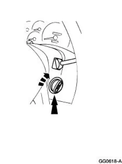
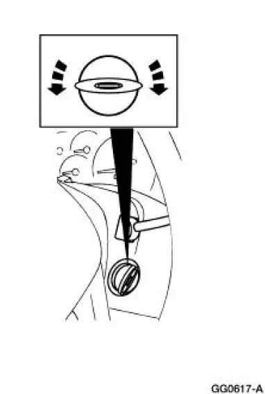
4. Twist off the cap from the ignition switch cylinder.
5. NOTE: The lock cylinder is repaired by discarding the inoperative lock cylinder and building a new lock cylinder using the appropriate lock repair package (F85Z-11582-AA). The lock repair package includes a detailed instruction sheet to build the new lock cylinder to the current key code of the vehicle.
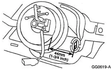
Remove the ignition switch lock cylinder.
- Use a 1/8-inch diameter drill bit to drill out the lock cylinder retaining pin.
- Use a 3/8-inch drill bit to drill down the middle of the ignition lock key slot until the ignition switch lock cylinder breaks loose.
- Remove and discard the ignition switch lock cylinder and clean the drill shavings from the steering column.
6. Remove the bearing retainer.
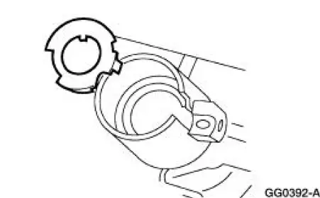
7. Remove the bearing and gear.
- Thoroughly clean all drill shavings from the steering column and inspect it for damage.
8. To install, reverse the removal procedure.
- Install a new ignition switch lock cylinder.
- Verify ignition switch lock cylinder operation.
9. WARNING: To avoid the risk of serious personal injury, read and follow all warnings, cautions, notes and instructions in the reactivation procedure.
Reactivate the supplemental restraint system (SRS). For additional information, refer to Supplemental Restraint System (SRS) Deactivation and Reactivation in this section.
 Ignition Switch Lock Cylinder - Functional
Removal and Installation
1. Disconnect the battery ground cable.
2. Remove the ignition switch lock cylinder (11582).
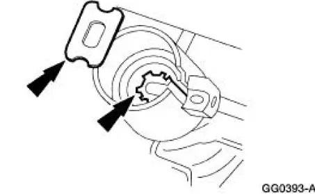
1. Insert the ignition key and turn to the RUN position.
2. Using a 1/8-in ...
 Wheel
Wheel
Removal and Installation
1. Disconnect the battery ground cable (14301) and wait at least one minute
to allow the depletion
of the restraint system backup power supply.
2. Turn the steering wheel ...
Other materials:
Fuel Injectors
Removal
WARNING: Do not smoke or carry lighted tobacco or open flame of any
type when
working on or near any fuel related components. Highly flammable mixtures are
always present
and may be ignited. Failure to follow these instructions may result in personal ...
Leakage Inspection
CAUTION: Do not try to stop the fluid leak by increasing the torque
beyond specifications.
This may cause damage to the case threads.
Check the fluid filler tube connection at the transmission case. If
leakage is found here, install a new
grommet.
Ch ...
Air Bag Supplemental Restraint System (SRS) (Description and Operation)
The air bag supplemental restraint system (SRS) is designed to provide
increased collision protection
for front seat occupants in addition to that provided by the three-point safety
belt system. Safety belt
use is necessary to obtain the best occupant protec ...
