Ford Mustang (1999-2004) Service Manual: Inspection and Verification

1. The keyless entry system is a generic electronic module (GEM).

2. Verify the customer concern by using the remote transmitters to operate the keyless entry system.

3. Visually inspect for the following obvious signs of mechanical and electrical damage.

Visual Inspection Chart

Mechanical Electrical
  • Binding latches
  • CJB Fuses:
  • 39 (5A)
  • 19 (15A)
  • 25 (25A)
  • BJB Fuse POWER WINDOWS (40A)
  • Damaged wiring harness
  • Loose or corroded connector(s)
  • Circuitry open/shorted
  • Damaged relays
  • Remote transmitter
  • Remote transmitter batteries

4. If the concern remains after the inspection, connect the scan tool to the data link connector (DLC) located beneath the instrument panel and select the vehicle to be tested from the scan tool menu. If the scan tool does not communicate with the vehicle:

  • check that the program card is correctly installed.
  • check the connections to the vehicle.
  • check the ignition switch position.

5. If the scan tool still does not communicate with the vehicle, refer to the scan tool manual.

6. Carry out the DATA LINK DIAGNOSTIC TEST. If the scan tool responds with:

  • CKT914, CKT915 or CKT70 = ALL ECUS NO RESP/NOT EQUIP, refer to Section.
  • NO RESP/NOT EQUIP for GEM, go to Pinpoint Test A.
  • SYSTEM PASSED, retrieve and record the continuous diagnostic trouble codes (DTCs), erase the continuous DTCs, and carry out the self-test diagnostics for the GEM.

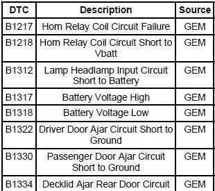
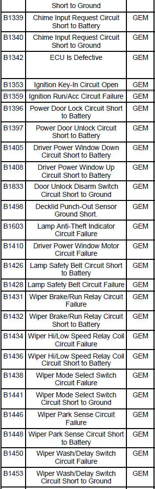
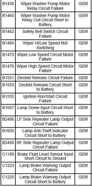
7. If the DTCs retrieved are related to the concern, go to the GEM Diagnostic Trouble Code (DTC) Index to continue diagnostics.

8. If no DTCs related to the concern are retrieved, proceed to Symptom Chart to continue diagnostics.

GEM Diagnostic Trouble Code (DTC) Index

GEM Diagnostic Trouble Code (DTC) Index

GEM Diagnostic Trouble Code (DTC) Index

GEM Diagnostic Trouble Code (DTC) Index

Symptom Chart

Condition Possible Sources Action
  • No communication with the generic electronic module
  • Circuitry.
  • CJB Fuse 39 (5A).
  • GEM.
  • GO to Pinpoint Test A .
  • All door locks are inoperative
  • CJB Fuse 19 (15A).
  • BJB Fuse POWER WINDOWS (40A).
  • Circuitry.
  • GEM.
  • Switches.
  • Lock actuators.
  • GO to Pinpoint Test B .
  • The doors do not lock/unlock using the remote transmitter
  • Ignition switch.
  • GEM.
  • Remote transmitter.
  • Remote transmitter batteries.
  • GO to Pinpoint Test C .
  • The luggage compartment door is inoperative using the remote transmitter
  • CJB Fuse 25 (25A).
  • Remote transmitter batteries.
  • Remote transmitter.
  • GEM.
  • Circuitry.
  • Luggage compartment lid release relay.
  • GO to Pinpoint Test D .
  • Panic function does not operate correctly
  • GEM.
  • Driver door unlock relay.
  • Circuitry.
  • Remote transmitter and batteries.
  • Courtesy lamps.
  • Horn relay.
  • Horn.
  • Parklamps.
  • GO to Pinpoint Test E .

Pinpoint Tests

PINPOINT TEST A: NO COMMUNICATION WITH THE GENERIC ELECTRONIC MODULE

Test Step Result / Action to Take
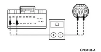
CAUTION: Use the correct probe adapter(s) when making measurements. Failure to use the correct probe adapter(s) may damage the connector.
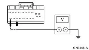
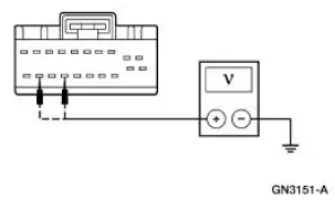
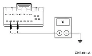
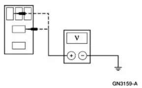
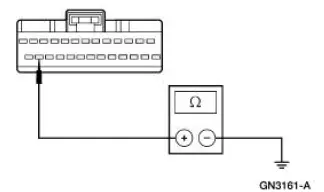
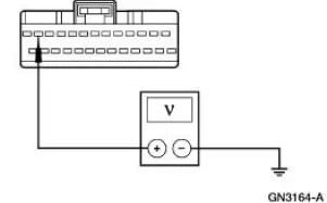
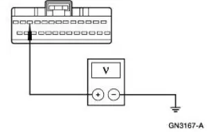
A1 CHECK THE GENERIC ELECTRONIC MODULE (GEM) POWER SUPPLY Yes

GO to A2 .

No

REPAIR the circuit(s) in question. TEST the system for normal operation.

  • Key in OFF position.
  • Disconnect: Generic Electronic Module (GEM) C201a.
  • Disconnect: GEM C201b.
  • Key in ON position.
  • Using the following table, measure the voltage between the GEM, harness side and ground.

  • Are the voltages greater than 10 volts?
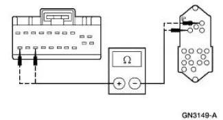
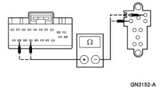
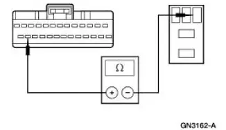
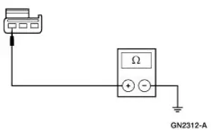
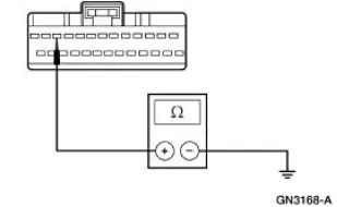
A2 CHECK THE GEM GROUND CIRCUIT 397 (BK/WH) FOR OPEN Yes

GO to A3 .

No

REPAIR the circuit(s) in question. TEST the system for normal operation

  • Key in OFF position.
  • Measure the reistance between the GEM C201b pin 4, circuit 397 (BK/WH), harness side and ground.

  • Is the reistance less than 5 ohms?
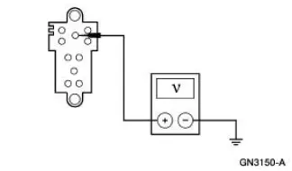
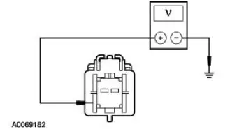
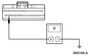
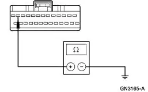
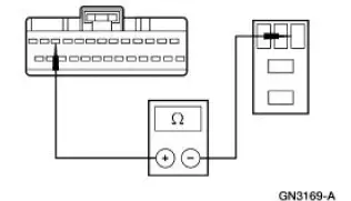
A3 CHECK CIRCUIT 397 (BK/WH) FOR SHORT TO POWER Yes

REPAIR the circuit. TEST the system for normal operation.

No

REFER to Section

  • Measure the voltage between the GEM C201b pin 4, circuit 397 (BK/WH), harness side and ground.

  • Is any voltage present?

PINPOINT TEST B: ALL DOOR LOCKS ARE INOPERATIVE

Test Step Result / Action to Take
B1 CHECK POWER LOCK INPUTS TO THE GEM Yes

GO to B11 .

No

GO to B2 .

  • Connect the diagnostic tool.
  • Monitor the GEM PIDS DR_LOCK, DR_UNLK, PD_LOCK, PD_UNLK, while depressing the driver and passenger power door lock and unlock switches.
  • Do the PID values agree with the switch positions?
B2 ISOLATE BETWEEN THE DRIVER AND PASSENGER POWER DOOR LOCK SWITCHES Yes

GO to B7 .

No

GO to B3 .

NOTE: This PID may not be supported in the normal scan tool PID list. It can be located in the Function test - "Transmitter Tic/Data".

When this test is activated, the appropriate results may be obtained when pressing the keyfob buttons.

  • Connect the diagnostic tool.
  • Monitor the GEM PIDS DR_LOCK and DR_UNLK, while depressing the driver power door lock and unlock switches.
  • Do the PID values agree with the switch positions?
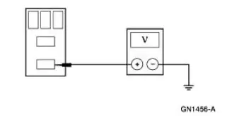
B3 CHECK CIRCUIT 326 (WH/VT) FOR VOLTAGE - DRIVER SIDE Yes

GO to B4 .

No

REPAIR Circuit 326 (WH/VT). REPEAT the self-test. CLEAR the DTCs.

  • Disconnect: Master Window/Door Lock Control Switch C508.
  • Measure the voltage between master window/door lock control switch C508 Pin 3, Circuit 326 (WH/VT), harness side and ground.

  • Is the voltage greater than 10 volts?
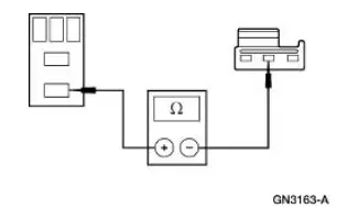
B4 CHECK THE DRIVER POWER DOOR LOCK SWITCH FOR CORRECT OPERATION Yes

GO to B5 .

No

INSTALL a new master window/door lock control switch.

REPEAT the selftest.

CLEAR the DTCs.

  • Carry out the master window/door lock control switch component test. REFER to Wiring Diagrams Cell 149, Component Testing.
  • Is the master window/door lock control switch OK?
B5 CHECK CIRCUITS 129 (LG) AND 1014 (VT) FOR SHORT TO POWER Yes

REPAIR the circuit in question. REPEAT the self-test. CLEAR the DTCs.

No

GO to B6 .

  • Key in OFF position.
  • Disconnect: GEM C201c.
  • Measure the voltage between GEM C201c Pin 20, Circuit 129 (LG), harness side and ground; and between GEM C201c Pin 18, Circuit 1014 (VT), harness side and ground.

  • Key in ON position.
  • Measure the voltage between GEM C201c Pin 20, Circuit 129 (LG), harness side and ground; and between GEM C201c Pin 18, Circuit 1014 (VT), harness side and ground.

  • Key in OFF position.
  • Are the voltages greater than 10 volts?
B6 CHECK CIRCUITS 129 (LG) AND 1014 (VT) FOR OPEN Yes

INSTALL a new GEM. For additional information, REFER to Section.

REPEAT the selftest.

CLEAR the DTCs.

No

REPAIR the circuit in question. REPEAT the self-test. CLEAR the DTCs.

  • Measure the resistance between master window/door lock control switch C508 Pin 4, Circuit 129 (LG), harness side and GEM C201c Pin 20, Circuit 129 (LG), harness side; and between master window/door lock control switch C508 Pin 2, Circuit 1014 (VT), harness side and GEM C201c 2 Pin 18, Circuit 129 (LG), harness side.

  • Are the resistances less than 5 ohms?
B7 CHECK CIRCUIT 326 (WH/VT) FOR VOLTAGE - PASSENGER SIDE Yes

GO to B8 .

No

REPAIR Circuit 326 (WH/VT). REPEAT the self-test. CLEAR the DTCs.

  • Disconnect: Passenger Window/Door Lock Control Switch C629.
  • Measure the voltage between passenger/window door lock control switch C629 Pin 3, Circuit 326 (WH/VT), harness side and ground

  • Is the voltage greater than 10 volts?
B8 CHECK THE PASSENGER POWER DOOR LOCK SWITCH FOR CORRECT OPERATION Yes

GO to B9 .

No

INSTALL a new master window/door lock control switch.

REPEAT the selftest.

CLEAR the DTCs.

  • Carry out the passenger window/door lock control switch component test. REFER to Wiring Diagrams Cell 149, Component Testing.
  • Is the master window/door lock control switch OK?
B9 CHECK CIRCUITS 119 (PK/YE) AND 120 (PK/LG) FOR SHORT TO POWER Yes

REPAIR the circuit in question. REPEAT the self-test. CLEAR the DTCs.

No

GO to B10 .

  • Disconnect: GEM C201c.
  • Measure the voltage between GEM C201c Pin 19, Circuit 119 (PK/YE), harness side and ground; and between GEM C201c Pin 17, Circuit 120 (PK/LG), harness side and ground.

  • Key in ON position.
  • Measure the voltage between GEM C201c Pin 19, Circuit 119 (PK/YE), harness side and ground; and between GEM C201c Pin 17, Circuit 120 (PK/LG), harness side and ground.

  • Key in OFF position.
  • Are the voltages greater than 10 volts?
B10 CHECK CIRCUITS 119 (PK/YE) AND 120 (PK/LG) FOR OPEN Yes

INSTALL a new GEM. For additional information, REFER to Section.

REPEAT the selftest.

CLEAR the DTCs.

No

REPAIR the circuit in question. REPEAT the self-test. CLEAR the DTCs.

  • Measure the resistance between passenger window/door lock control switch C629 Pin 2, Circuit 119 (PK/YE), harness side and GEM C201c Pin 19, Circuit 119 (PK/YE), harness side; and between passenger window/door lock control switch C629 Pin 4, Circuit 120 (PK/LG), harness side and GEM C201c Pin 17, Circuit 120 (PK/LG), harness side.

  • Are the resistances less than 5 ohms?
B11 CHECK GEM CONTROL OF THE POWER DOOR LOCKS Yes

INSTALL a new GEM. For additional information, REFER to Section.

REPEAT the selftest.

CLEAR the DTCs.

No

GO to B12 .

  • Connect the diagnostic tool.
  • Trigger the GEM active command LOCK, UNLOCK, DD UNLOCK, and DD LOCK ON and OFF.
  • Do the doors lock and unlock?
B12 ISOLATE BETWEEN DRIVER AND PASSENGER POWER LOCK ACTUATORS Yes

GO to B17 .

No

GO to B13 .

  • Connect the diagnostic tool.
  • Trigger the GEM active command LOCK and DD UNLOCK ON and OFF.
  • Did the driver door lock and unlock?
B13 CHECK THE DRIVER POWER LOCK ACTUATOR OPERATION Yes

GO to B14 .

No

INSTALL a new driver door lock actuator. For additional information, REFER to Actuator .

REPEAT the selftest.

CLEAR the DTCs.

  • Disconnect: Driver Door Lock Actuator C525.
  • Momentarily connect a fused (40A) jumper wire between battery and driver door lock actuator Pin 1, component side; and connect a jumper wire between ground and driver door lock actuator Pin 2, component side.

  • Reverse the jumper wire connections and momentarily connect.

  • Did the driver door lock and unlock?
B14 CHECK CIRCUIT 193 (YE/LG) FOR OPEN Yes

GO to B15 .

No

REPAIR Circuit 193 (YE/LG). REPEAT the self-test. CLEAR the DTCs.

NOTE: Verify voltage at BJB Fuse POWER WINDOWS (40A) before completing this step.
  • Disconnect: GEM C201b.
  • Measure the voltage between GEM C201b Pin 3, Circuit 193 (YE/LG), harness side and ground.

  • Is the voltage greater than 10 volts?
B15 CHECK CIRCUIT 1205 (BK) FOR OPEN Yes

GO to B16 .

No

REPAIR Circuit 1205 (BK). REPEAT the self-test. CLEAR the DTCs.

  • Measure the resistance between GEM C201b Pin 1, Circuit 1205 (BK), harness side and ground.

  • Is the resistance less than 5 ohms?
B16 CHECK CIRCUITS 163 (PK/YE) AND 1015 (RD/WH) FOR OPEN Yes

INSTALL a new GEM. For additional information, REFER to Section.

REPEAT the selftest.

CLEAR the DTCs.

No

REPAIR the circuit in question. REPEAT the self-test. CLEAR the DTCs.

  • Disconnect: GEM C201c.
  • Measure the resistance between driver door lock actuator C525 Pin 2, Circuit 1015 (RD/WH), harness side and GEM C201c Pin 9, Circuit 1015 (RD/WH), harness side; and between driver door lock actuator C525 Pin 1, Circuit 163 (RD/OG), harness side, and GEM C201c Pin 7, Circuit 163 (RD/OG), harness side.

  • Are the resistances less than 5 ohms?
B17 CHECK THE PASSENGER POWER LOCK ACTUATOR OPERATION Yes

GO to B18 .

No

INSTALL a new passenger door lock actuator. REFER to Actuator . REPEAT the self-test. CLEAR the DTCs.

  • Disconnect: Passenger Door Lock Actuator C603.
  • Momentarily connect a fused (40A) jumper wire between battery and passenger door lock actuator Pin 1, component side; and connect a jumper wire between ground and passenger door lock actuator Pin 2, component side.

  • Reverse the jumper wire connections and momentarily connect.

  • Did the passenger door lock and unlock?
B18 CHECK CIRCUITS 163 (RD/OG), 1015 (RD/WH), 117 (PK/BK), AND 118 (PK/OG) FOR OPEN Yes

INSTALL a new GEM. For additional information, REFER to Section.

REPEAT the selftest.

CLEAR the DTCs.

No

REPAIR the circuit in question. REPEAT the self-test. CLEAR the DTCs.

  • Disconnect: GEM C201c.
  • Measure the resistance between passenger door lock actuator C603 Pin 2, Circuit 1015 (RD/WH), harness side and GEM C201c Pin 10, Circuit 117 (PK/BK), harness side; and between passenger door lock actuator C603 Pin 1, Circuit 163 (RD/OG), harness side, and GEM C201c Pin 8, Circuit 118 (PK/OG), harness side.

  • Are the resistances less than 5 ohms?

PINPOINT TEST C: THE DOORS DO NOT LOCK/UNLOCK USING THE REMOTE TRANSMITTER

Test Step Result / Action to Take
C1 CHECK THE LOCK OPERATION USING THE DRIVER DOOR LOCK SWITCH Yes

GO to C2 .

No

GO to Pinpoint Test B .

  • Lock and unlock the doors using the driver door lock switch.
  • Do all the doors lock and unlock correctly?
C2 CHECK IGNITION STATES Yes

GO to C3 .

No

For key-in-ignition concerns, REFER to Section .

  • Connect the diagnostic tool.
  • Monitor the GEM PIDS IGN_KEY, IGN_A, IGN_S, and IGN_R while cycling the ignition switch through the OFF, ACC, RUN, START and key out positions.
  • Do the PID values agree with the ignition switch positions?
C3 CHECK THE GEM FUNCTION TEST TIC/DATA Yes

INSTALL a new GEM. For additional information, REFER to Section.

REPEAT the self-test. CLEAR the DTCs.

No

GO to C4 .

NOTE: This PID may not be supported in the normal scan tool PID list. It can be located in the Function Test - "Transmitter Tic/DATA". When this test is activated, the appropriate results may be obtained when pressing the keyfob buttons.
  • Remove the ignition key from the ignition.
  • Connect the diagnostic tool.
  • Monitor the GEM FUNCTION TEST TIC/DATA while pressing the lock and unlock buttons on the remote transmitter.
  • Does LAST DATA RECEIVED match the button presses of the remote transmitter?
C4 CHECK THE BATTERIES IN THE REMOTE TRANSMITTER Yes

SYSTEM is OK. REPEAT the self-test.

CLEAR the DTCs.

No

GO to C5 .

  • Install new batteries in the remote transmitter.
  • Connect the diagnostic tool.
  • Monitor the GEM FUNCTION TEST TIC/DATA while pressing the lock and unlock buttons on the remote transmitter.
  • Does LAST DATA RECEIVED match the button presses of the remote transmitter?
C5 REPROGRAM THE REMOTE TRANSMITTERS TO THE GEM Yes

SYSTEM is OK. REPEAT the self-test.

CLEAR the DTCs.

No

PROGRAM a new remote transmitter to the vehicle. For additional information, REFER to Programming-Keyless Entry Remote Transmitter . REPEAT the self-test. CLEAR the DTCs. If the problem still remains, INSTALL a new GEM and program the remote transmitters to the vehicle. For additional information, REFER to Section .

REPEAT the self-test. CLEAR the DTCs.

  • NOTE: When carrying out the following procedure it must be noted that all previous programmed remote transmitters will be erased. The customer needs to be informed that any remote transmitters not present during the programming mode will not operate the vehicle. All remote transmitters must be programmed at the same time.
  • Reprogram the remote transmitter to the GEM. For additional information, refer to Programming-Keyless Entry Remote Transmitter .
  • Connect the diagnostic tool.
  • Monitor the GEM FUNCTION TEST TIC/DATA while pressing the lock and unlock buttons on the remote transmitter.
  • Does LAST DATA RECEIVED match the button presses of the remote transmitter?

PINPOINT TEST D: THE LUGGAGE COMPARTMENT DOOR IS INOPERATIVE USING THE REMOTE TRANSMITTER

Test Step Result / Action to Take
D1 CHECK IGNITION STATES Yes

GO to D2 .

No

REFER to Section for key-in-ignition warning chime concerns

  • Connect the diagnostic tool.
  • Monitor the GEM PIDS IGN_KEY, IGN_A, IGN_S, and IGN_R while cycling the ignition switch through the OFF, ACC, RUN, START and key out positions.
  • Do the PID values agree with the ignition switch positions?
D2 CHECK THE GEM PID LAST DATA RECEIVED FOR LUGGAGE COMPARTMENT Yes

GO to D5 .

No

GO to D3 .

  • Remove the ignition key from the ignition.
  • Connect the diagnostic tool.
  • Monitor the GEM PID LAST DATA RECEIVED while pressing and releasing the luggage compartment, panic, lock, and unlock buttons of the remote transmitter.
  • Does LAST DATA RECEIVED match the button presses of the remote transmitter?
D3 CHECK THE BATTERIES IN THE REMOTE TRANSMITTER Yes

SYSTEM is OK. REPEAT the self-test. CLEAR the DTCs.

No

GO to D4 .

  • Install new batteries in the remote transmitter.
  • Connect the diagnostic tool.
  • Monitor the GEM FUNCTION TEST TIC/DATA while pressing the luggage compartment button on the remote transmitter.
  • Does LAST DATA RECEIVED match the button presses of the remote transmitter?
D4 REPROGRAM THE REMOTE TRANSMITTERS TO THE GEM Yes

SYSTEM is OK. REPEAT the self-test. CLEAR the DTCs.

No

PROGRAM a new remote transmitter to the vehicle. For additional information, REFER to Programming-Keyless Entry Remote Transmitter .

REPEAT the self-test. CLEAR the DTCs. If the problem still remains, INSTALL a new GEM and program the remote transmitters to the vehicle. For additional information, REFER to Section. REPEAT the self-test. CLEAR the DTCs.

  • NOTE: When carrying out the following procedure, it must be noted that all previous programmed remote transmitters will be erased. The customer needs to be informed that any remote transmitters not present during the programming mode will not operate the vehicle. All remote transmitters must be programmed at the same time.
  • Reprogram the remote transmitter to the GEM. For additional information, refer to Programming-Keyless Entry Remote Transmitter
  • Connect the diagnostic tool.
  • Monitor the GEM FUNCTION TEST TIC/DATA while pressing the lock and unlock buttons on the remote transmitter.
  • Does LAST DATA RECEIVED match the button presses of the remote transmitter?
D5 CHECK THE GEM OUTPUT TO THE LUGGAGE COMPARTMENT Yes

INSTALL a new GEM. For additional information, REFER to Section. REPEAT the self-test. CLEAR the DTCs.

No

GO to D6 .

  • Trigger the GEM active command RELEASE to ON and OFF.
  • Did the luggage compartment release?
D6 CHECK CIRCUIT 931 (OG) FOR OPEN Yes

GO to D7 .

No

REPAIR Circuit 931 (OG).

REPEAT the self-test. CLEAR the DTCs.

  • Disconnect: Luggage Compartment Lid Release Relay.
  • Measure the voltage between luggage compartment lid release relay Pin 2, Circuit 931 (OG), harness side and ground; and between luggage compartment lid release relay Pin 5 Circuit 931 (OG), harness side and ground

  • Is the voltage greater than 10 volts?
D7 BYPASS THE GEM AND RELAY CONTROL Yes

GO to D8 .

No

GO to D12 .

  • Momentarily connect a 25A jumper wire between the luggage compartment lid release relay Pin 3 and Pin 5.

  • Did the luggage compartment lid release?
D8 CHECK LUGGAGE COMPARTMENT LID RELEASE RELAY Yes

GO to D9 .

No

INSTALL a new luggage compartment lid release relay.

REPEAT the self-test. CLEAR the DTCs.

  • Carry out the luggage compartment lid release relay.

    REFER to Wiring Diagrams Cell 149, Component Testing.

  • Is the luggage compartment lid release relay OK?
D9 CHECK CIRCUIT 599 (PK/LG) FOR SHORT TO POWER Yes

REPAIR Circuit 599 (PK/LG).

REPEAT the self-test. CLEAR the DTCs.

No

GO to D10

  • Disconnect: GEM C201c.
  • Measure the voltage between GEM C201c Pin 25, Circuit 599 (PK/LG), harness side and ground.

  • Is the voltage greater than 10 volts?
D10 CHECK CIRCUIT 599 (PK/LG) FOR SHORT TO GROUND Yes

GO to D11 .

No

REPAIR Circuit 599 (PK/LG).

REPEAT the self-test. CLEAR the DTCs.

  • Measure the resistance between GEM C201c Pin 25, Circuit 599 (PK/LG), harness side and ground.

  • Is the resistance greater than 10,000 ohms?
D11 CHECK CIRCUIT 599 (PK/LG) FOR OPEN Yes

INSTALL a new GEM. For additional information, REFER to Section. REPEAT the self-test. CLEAR the DTCs.

No

REPAIR Circuit 599 (PK/LG).

REPEAT the self-test. CLEAR the DTCs.

  • Measure the resistance between GEM C201c Pin 25, Circuit 599 (PK/LG), harness side and luggage compartment lid release relay Pin 1, Circuit 599 (PK/LG), harness side.

  • Is the resistance less than 5 ohms?
D12 CHECK CIRCUIT 84 (VT/YE) FOR SHORT TO POWER Yes

REPAIR Circuit 84 (VT/YE).

REPEAT the self-test. CLEAR the DTCs.

No

GO to D13 .

  • Disconnect: GEM C201c.
  • Measure the voltage between luggage compartment lid release relay Pin 3, Circuit 84 (VT/YE), harness side and ground.

  • Is the voltage greater than 10 volts?
D13 CHECK CIRCUIT 84 (VT/YE) FOR OPEN Yes

GO to D14 .

No

REPAIR Circuit 84 (VT/YE).

REPEAT the self-test. CLEAR the DTCs.

  • Disconnect: Luggage Compartment Lid Release Solenoid C430.
  • Measure the resistance between luggage compartment lid release relay Pin 3, Circuit 84 (VT/YE), harness side and luggage compartment lid release solenoid C430 Pin 2, Circuit 84 (VT/YE), harness side.

  • Is the resistance less than 5 ohms?
D14 CHECK CIRCUIT 1205 (BK) FOR OPEN Yes

INSTALL a new luggage compartment lid release switch. REPEAT the self-test.

CLEAR the DTCs.

No

REPAIR Circuit 1205 (BK).

REPEAT the self-test. CLEAR the DTCs.

  • Measure the resistance between luggage compartment lid release solenoid C430 Pin 1, Circuit 1205 (BK), harness side and ground.

  • Is the resistance less than 5 ohms?

PINPOINT TEST E: PANIC FUNCTION DOES NOT OPERATE CORRECTLY

Test Step Result / Action to Take
E1 CHECK IGNITION STATES Yes

GO to E2 .

No

REFER to Section

  • Connect the diagnostic tool.
  • Monitor the GEM PIDS IGN_KEY, IGN_A, IGN_S, and IGN_R while cycling the ignition switch through the OFF, ACC, RUN, START and key out positions.
  • Do the PID values agree with the ignition switch positions?
E2 CHECK THE GEM PID LAST DATA RECEIVED FOR PANIC Yes

GO to E3 .

No

GO to Pinpoint Test D .

  • Remove the ignition key from the ignition.
  • Connect the diagnostic tool.
  • Monitor the GEM PID LAST DATA RECEIVED while pressing and releasing the luggage compartment, panic, lock, and unlock buttons of the remote transmitter.
  • Does LAST DATA RECEIVED match the button presses of the remote transmitter?
E3 CHECK THE COURTESY LAMPS Yes

GO to E4 .

No

REFER to Section

  • Connect the diagnostic tool.
  • Trigger the GEM active command COURTESYL ON and OFF.
  • Do the courtesy lamps illuminate and turn off?
E4 CHECK THE GEM OUTPUT TO THE HORN Yes

GO to E5 .

No

GO to E6

  • Connect the diagnostic tool.
  • Trigger the GEM active command HORN ON and OFF.
  • Did the horn sound and turn off?
E5 CHECK THE GEM OUTPUT TO THE PARKING LAMPS Yes

INSTALL a new GEM. For additional information, REFER to Section. REPEAT the self-test.

CLEAR the DTCs.

No

GO to E10 .

  • Connect the diagnostic tool.
  • Trigger the GEM active command PARKLAMPS ON and OFF.
  • Did the parking lamps illuminate and turn off?
E6 CHECK CIRCUIT 6 (YE/LG) FOR SHORT TO POWER Yes

GO to E7 .

No

REPAIR Circuit 6 (YE/LG).

REPEAT the self-test.

CLEAR the DTCs.

  • Disconnect: Horn Relay.
  • Disconnect: GEM C201c.
  • Measure the voltage between GEM C201c Pin 12, Circuit 6 (YE/LG), harness side and ground.

  • Is the voltage greater than 10 volts?
E7 CHECK CIRCUIT 6 (YE/LG) FOR SHORT TO GROUND Yes

GO to E8 .

No

REPAIR Circuit 6 (YE/LG).

REPEAT the self-test.

CLEAR the DTCs.

  • Measure the resistance between GEM C201c Pin 12, Circuit 6 (YE/LG), harness side and ground.

  • Is the resistance greater than 10,000 ohms?
E8 CHECK CIRCUIT 6 (YE/LG) FOR OPEN Yes

GO to E9 .

No

REPAIR Circuit 6 (YE/LG).

REPEAT the self-test.

CLEAR the DTCs.

  • Measure the resistance between GEM C201c Pin 12, Circuit 6 (YE/LG), harness side and horn relay Pin 1, Circuit 6 (YE/LG), harness side.

  • Is the resistance less than 5 ohms?
E9 CHECK THE HORN FOR NORMAL OPERATION Yes

INSTALL a new GEM. For additional information, REFER to Section. REPEAT the self-test.

CLEAR the DTCs.

No

REFER to Section

  • Depress the steering wheel horn switch.
  • Did the horn sound?
E10 CHECK CIRCUIT 1032 (WH/BK) FOR SHORT TO POWER Yes

GO to E11 .

No

REPAIR Circuit 1032 (WH/BK). REPEAT the self-test. CLEAR the DTCs.

  • Disconnect: Parking Lamp Relay.
  • Disconnect: GEM C201e.
  • Measure the voltage between GEM C201e Pin 11, Circuit 1032 (WH/BK), harness side and ground.

  • Is the voltage greater than 10 volts?
E11 CHECK CIRCUIT 1032 (WH/BK) FOR SHORT TO GROUND Yes

GO to E12 .

No

REPAIR Circuit 1032 (WH/BK). REPEAT the self-test. CLEAR the DTCs.

  • Measure the resistance between GEM C201e Pin 11, Circuit 1032 (WH/BK), harness side and ground.

  • Is the resistance greater than 10,000 ohms?
E12 CHECK CIRCUIT 1032 (WH/BK) FOR OPEN Yes

GO to E13

No

REPAIR Circuit 1032 (WH/BK). REPEAT the self-test. CLEAR the DTCs.

  • Measure the resistance between GEM C201e Pin 11, Circuit 1032 (WH/BK), harness side and parking lamp relay Pin 1, Circuit 1032 (WH/BK), harness side.

  • Is the resistance less than 5 ohms?
E13 CHECK THE PARKING LAMPS FOR NORMAL OPERATION Yes

INSTALL a new GEM. For additional information, REFER to Section. REPEAT the self-test.

CLEAR the DTCs.

No

REFER to Section

  • Turn the parking lamps on with the headlamp switch.
  • Did the parking lamps turn on and off with the headlamp switch?


    Principles of Operation
    NOTE: Battery power and ground must be remove before disconnecting the GEM connectors to avoid setting false codes. Power Locks Operation The power locks feature allows the customer to lock a ...

    Keyless Entry/Computer Operated Locks
    Programming -Keyless Entry Remote Transmitter NOTE: All keyless entry remote transmitters (15K601) must be programmed at the same time. NOTE: All previous transmitter identification codes (TIC ...

    Other materials:

    Cabin air filter
    Note: Make sure you have a cabin air filter installed at all times. This prevents foreign objects from entering the system. Running the system without a filter in place could result in degradation or damage to the system. Your vehicle is equipped with a cabi ...

    Wheel Hub - Cobra
    Special Tool(s) 2-3 Jaw Puller 205-D026 (D80L-1013-A) or Equivalent Driver 205-199 (T83T-3132-A1) Front Hub Remover Replacer 204-069 (T81P-1104-C) Hub Bearing Remover 204-081 (T83P-1104-AH2) ...

    Camshaft End Play - OHC Engines
    Special Tool(s) Dial Indicator Gauge with Holding Fixture 100-002 (TOOL-4201-C) or equivalent 1. Remove the roller followers. Refer to the appropriate section in Group 303 for the procedure. 2. Use a Dial Indicator Gauge with Holding Fixt ...