Ford Mustang (1999-2004) Service Manual: Keyless Entry (Diagnosis and Testing)
Refer to Wiring Diagrams Cell 59 , Generic Electronic Module for schematic and connector information.
Refer to Wiring Diagrams Cell 111 , Remote Keyless Entry (RKE) for schematic and connector information.
Special Tool(s)
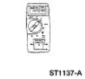 |
73 Digital Multimeter or equivalent 105-R0051 |
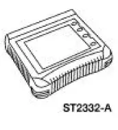 |
Worldwide Diagnostic System (WDS) 418-F224 New Generation STAR (NGS) Tester 418-F052, or equivalent scan tool |
 Switch - Door Lock
Removal
1. CAUTION: Place a rag between the window regulator switch
plate and the door trim
panel to avoid damaging the door trim panel.
Position the window regulator switch plate (14524) asi ...
 Principles of Operation
NOTE: Battery power and ground must be remove before disconnecting
the GEM connectors to avoid
setting false codes.
Power Locks Operation
The power locks feature allows the customer to lock a ...
Other materials:
Engine System - General Information
General Specifications
Engine
NOTE: This section contains information, steps and procedures that may
not be specific to your
engine.
This section covers general procedures and diagnosis and testing of the engine
system, except for
exhaust emission control ...
Throttle Body
Removal and Installation
WARNING: Do not smoke or carry lighted tobacco or open flame of any
type when
working on or near any fuel related components. Highly flammable mixtures are
always present
and can ignite. Failure to follow these instructions can resul ...
Spark Plugs
Special Tool(s)
Remover, Spark Plug Wire
303-106 (T74P-6666A)
Material
Item
Specification
Silicone Brake Caliper Grease
and Dielectric Compound
D7AZ-19A331-A or equivalent
ESE-M1C171-
A
Removal and Installation
CAUTION: ...
