Ford Mustang (1999-2004) Service Manual: Installation
WARNING: To reduce the risk of serious personal injury, read and follow all warnings, cautions and notes at the beginning of the removal procedure.
Vehicles receiving a new clockspring
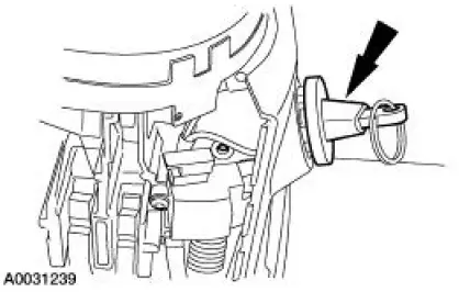
1. NOTE: A new clockspring is supplied in a centralized position and held there with a key.
Remove the key from the clockspring, holding the rotor in its centralized position.
- Do not allow the clockspring rotor to turn.
Vehicles needing clockspring recentering
2. WARNING: Incorrect centralization may result in premature component failure. If in doubt when centralizing the clockspring, repeat the centralizing procedure. Failure to follow this instruction may result in personal injury.
CAUTION: Make sure the road wheels are in the straight ahead position.
NOTE: If a clockspring has rotated out of center, follow through with this step.
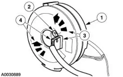
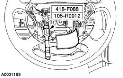
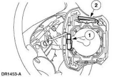
Centralize the clockspring.
1. Hold the clockspring outer housing stationary.
2. Depress the clockspring locking tab to release the rotor.
3. CAUTION: Overturning will destroy the clockspring. The internal ribbon wire acts as the stop and can be broken from its internal connection.
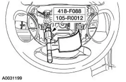
While holding the clockspring locking tab in the released position, turn the rotor counterclockwise, carefully feeling for the ribbon wire to run out of length, and a slight resistance is felt. Stop turning at this point.
4. While holding the clockspring locking tab in the released position, turn the clockspring clockwise approximately three turns. This is the center point of the clockspring.
- Release the clockspring locking tab. Do not allow the rotor to turn from this position.
All vehicles
3. NOTE: Slight turning of the clockspring rotor is allowable for alignment purposes to the steering column.
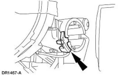
With the flats of the clockspring aligned to the flats of the steering column, slide the clockspring onto the steering column engaging the retaining tabs.
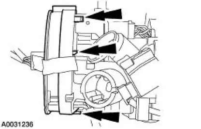
4. Route the clockspring wire harness down the side of the steering column and into the holders.
5. Remove the restraint system diagnostic tool from the vehicle harness side of the clockspring electrical connector.
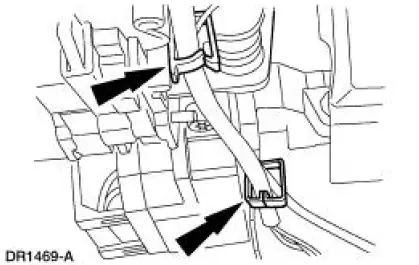
6. Connect the two clockspring electrical connectors. Position the clockspring electrical connectors onto the bracket.
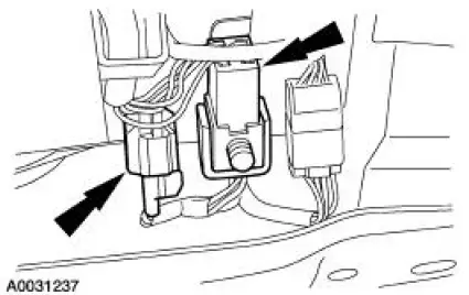
7. Install the key-in-ignition warning indicator switch.
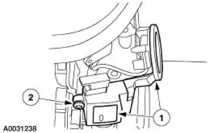
8. Install the passive anti-theft system (PATS) transmitter.
1. Position the PATS transmitter to the steering column.
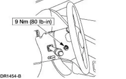
2. Install the screw.
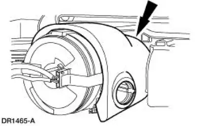
9. Reposition the upper steering column shroud.
10. Install the ignition switch lock cylinder.
Vehicle repairs reusing the same clockspring
11. Remove the tape applied during clockspring removal.
All vehicles
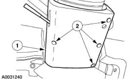
12. Install the lower steering column shroud.
1. Position the lower steering column shroud.
2. Install the screws.
13. Install the steering wheel. Do not install the driver air bag module at this time. For additional information, refer to Section.
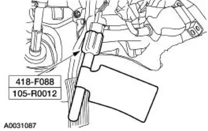
14. Attach the restraint system diagnostic tool to the clockspring electrical connector at the top of the steering column.
15. Connect the battery ground cable. For additional information, refer to Section.
16. With the restraint system diagnostic tools installed at all deployable devices, prove out the supplemental restraint system (SRS). For additional information, refer to Air Bag Supplemental Restraint System (SRS) , in the Diagnosis and Testing portion of this section.
17. Disconnect the battery ground cable and wait at least one minute. For additional information, refer to Section.
18. Remove the restraint system diagnostic tool from the clockspring electrical connector at the top of the steering column.
19. Connect and position the driver air bag module to the steering wheel.
1. Connect the driver air bag module electrical connector.
2. Position the driver air bag module to the steering wheel.
20. Install the two driver air bag module bolts.
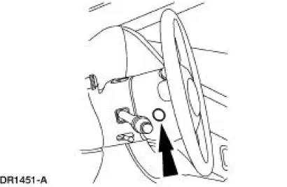
21. Install the two steering wheel back cover plugs.
22. Restore the vehicle to operating condition.
1. WARNING: To reduce the risk of serious personal injury, read and follow all warnings, cautions, notes, and instructions in the supplemental restraint system (SRS) deactivation/reactivation procedure.
Reactivate the supplemental restraint system (SRS). For additional information, refer to Supplemental Restraint System (SRS) Deactivation and Reactivation in the General Procedures portion of this section.
2. WARNING: The restraint system diagnostic tool is for restraint system service only. Remove from the vehicle prior to road use. Failure to remove could result in injury and possible violation of vehicle safety standards.
With all the restraint system diagnostic tools removed, prove out the supplemental restraint system (SRS). For additional information, refer to Air Bag Supplemental Restraint System (SRS) in the Diagnosis and Testing portion of this section.
 Removal
WARNING: Always wear safety glasses when repairing an air bag
supplemental restraint
system (SRS) vehicle and when handling an air bag module. This will
reduce the risk of injury
in the even ...
 Frame and Mounting
Frame and Body Mounting
Torque Specifications
Frame Assembly
Underbody misalignment can affect front and rear wheel alignment, the
operation of the suspension
parts and drivetrain operation. Window ...
Other materials:
Air Conditioning (A/C) Pressure Relief Valve - 3.8L
Material
Item
Specification
PAG Refrigerant Compressor
Oil (R-134a Systems)
F7AZ-19589-DA (Motorcraft YN-
12-C)
WSH-M1C231-
B
Removal and Installation
1. Recover the refrigerant. For additional information, refer to Section.
2. Unlat ...
Transmission Description (Description and Operation)
The 4R70W has the following features:
Wide ratio gears
Four speeds
Rear wheel drive
Automatic
Electronic shift
Torque converter clutch control
Line pressure controls
The transmission uses Ravigneaux-style double-pinion gearset with ...
Exterior Trim and Ornamentation
Torque Specifications
Exterior Trim and Ornamentation
The exterior trim and ornamentation consists of the following
components:
body side scoop
hood scoop (if equipped)
front spoiler (Mach 1)
radiator grille
rear spoiler (if equipped)
...
