Ford Mustang (1999-2004) Service Manual: Frame and Mounting
Frame and Body Mounting
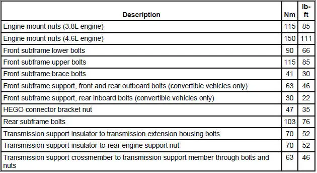
Torque Specifications
Frame Assembly
Underbody misalignment can affect front and rear wheel alignment, the operation of the suspension parts and drivetrain operation. Window glass cracks, door and window opening concerns, and air or water leaks at the doors are often caused by improperly tightened bolts and body misalignment.
Every structural member and outer panel is designed to offer the maximum protection in the event of a collision.
Body Misalignment Check
1. CAUTION: Do not attempt to correct any serious misalignment with one pulling/pushing operation. Damage to structure may occur.
NOTE: All body alignment measurements are made without trim and from metal to metal.
To check the body alignment, take two opposite diagonal measurements between the front, center or rear pillars. Take the measurements between reference points, such as crease lines or weld joints which are diagonally opposite each other on the two pillars being measured.
- Underbody Misalignment Check
- Front Subframe - 3.8L Engine
- Front Subframe - 4.6L (2V) Engine
- Front Subframe - 4.6L (4V) Engine
- Rear Subframe
 Installation
WARNING: To reduce the risk of serious personal injury, read
and follow all warnings,
cautions and notes at the beginning of the removal procedure.
Vehicles receiving a new clockspring
1. NOT ...
 Underbody Misalignment Check
Underbody Dimensions
1. Underbody dimensions tolerances are +- 3.175 mm (0.125 in). Reference
dimensions are not
controlled dimensions. Reference points are +- 4.76 mm (0.1875 in). All und ...
Other materials:
Interior luggage compartment release
WARNING: Keep vehicle doors and luggage compartment locked
and keep keys and remote transmitters out of a child’s reach.
Unsupervised children could lock themselves in the trunk and risk
injury. Children should be taught not to play in vehicles.
WARNING: Do ...
Exhaust Manifold to Exhaust Gas Recirculation (EGR)
Valve Tube
Removal and Installation
NOTE: 3.8L shown, 4.6L (2V) similar.
1. With the vehicle in NEUTRAL, position it on a hoist.
2. Disconnect the exhaust gas recirculation (EGR) valve tube from the
exhaust manifold.
3. Remove the differential feedback exhaust ga ...
Transmission Electronic Control System
The powertrain control module (PCM) and its input/output network
control the following transmission
operations:
Shift timing
Line pressure (shift feel)
Torque converter clutch
The transmission control is separate from the engine control s ...
