Ford Mustang (1999-2004) Service Manual: Installation
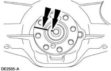
1. Inspect the rear axle pinion flange seal journal for rust, nicks, and scratches prior to installing the flange. Polish the seal journal with fine crocus cloth, if necessary.
2. Lubricate the rear axle pinion flange splines.
- Use SAE 75W-140 High Performance Rear Axle Lubricant F1TZ-19580-B or equivalent meeting Ford specification WSL-M2C192-A.
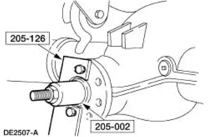
3. NOTE: Disregard the index marks if installing a new rear axle pinion flange.
Position the rear axle pinion flange.
4. Using the special tools, install the rear axle pinion flange.
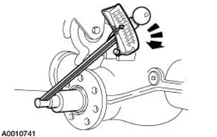
5. CAUTION: Do not under any circumstance loosen the nut to reduce preload. If it is necessary to reduce preload, install a new differential drive pinion collapsible spacer (4662) and nut.
Tighten the nut to set the preload.
- Rotate the pinion occasionally to make sure the pinion bearings (4630) (4621) seat correctly. Take frequent pinion bearing torque preload readings by rotating the drive pinion gear with a Nm (inch/pound) torque wrench.
- If the preload recorded prior to disassembly is lower than the specification for used bearings, then tighten the nut to specification. If the preload recorded prior to disassembly is higher than the specification for used bearings, then tighten the nut to the original reading as recorded.
- Refer to the torque specification for used pinion bearings in the Specifications portion of this section.
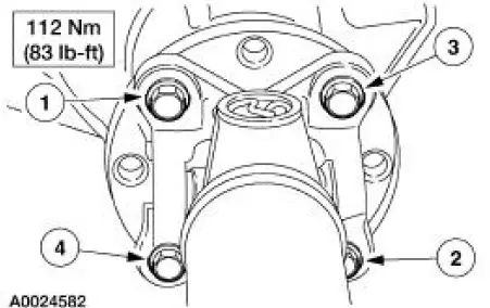
6. CAUTION: Align the index-marks.
CAUTION: Install the driveshaft with new bolts. If new bolts are not available, apply Threadlock and Sealer EOAZ-19554-AA or equivalent meeting Ford specification WSKM2G351- A5 to the threads of the original bolts.
CAUTION: The driveshaft centering socket yoke fits tightly on the rear axle pinion flange pilot. To make sure that the yoke seats squarely on the flange, tighten the bolts evenly in a cross pattern as shown.
Connect the driveshaft.
7. Install the rear brake calipers.
8. Install the rear wheel and tire assemblies.
9. Lower the vehicle.
 Removal
1. Raise and support the vehicle.
2. Remove the rear wheel and tire assemblies.
3. CAUTION: Remove the rear brake calipers to prevent drag during the
drive pinion
bearing preload adjustment.
CAU ...
 Pinion Seal
Special Tool(s)
Installer, Drive Pinion Oil Seal
205-133 (T79P-4676-A)
Removal
1. Remove the pinion flange (4851). For additional information, refer to
Drive Pinion Flange in this
sec ...
Other materials:
Hose
Special Tool(s)
Installer Set, Teflon Seal
211-D027 (D90P-3517-A) or
equivalent
Removal and Installation
CAUTION: While servicing the power steering system, make sure to plug
all open hoses,
line fittings, and fluid ports to prevent the entr ...
Rear Drive Axle/Differential - Ford 7.5-Inch Ring Gear
General Specifications
a: In-vehicle repair refill capacities are determined by filling the rear axle
with the specified lubricant to
6.4-14.3-mm (1/4-9/16-in) below the bottom of the fill hole.
Torque Specifications
...
Getting assistance outside the U.S. And Canada
Before exporting your vehicle to a foreign country, contact the
appropriate foreign embassy or consulate. These officials can inform you
of local vehicle registration regulations and where to find unleaded fuel.
If you cannot find unleaded fuel or can only ge ...
