Ford Mustang (1999-2004) Service Manual: Removal
1. Raise and support the vehicle.
2. Remove the rear wheel and tire assemblies.
3. CAUTION: Remove the rear brake calipers to prevent drag during the drive pinion bearing preload adjustment.
CAUTION: Do not allow the calipers to hang from the brake hoses.
Remove the rear brake caliper and support bracket from the knuckle as an assembly. Wire the caliper and support bracket assembly out of the way.
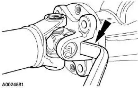
4. CAUTION: Index-mark the driveshaft flange and rear axle pinion flange (4851) to maintain initial balance during installation.
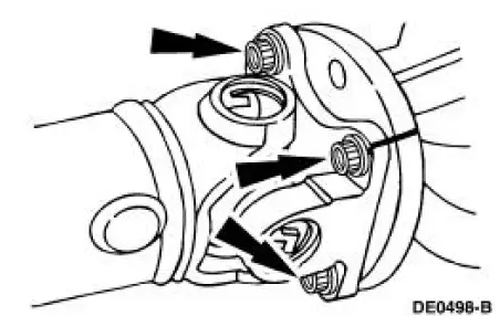
CAUTION: The driveshaft centering socket yoke fits tightly on the rear axle pinion flange pilot. Never hammer on the driveshaft (4602) or any of its components to disconnect the yoke from the flange. Pry only in the area shown, with a suitable tool, to disconnect the yoke from the flange.
Disconnect and position the driveshaft out of the way.
5. Install an Nm (inch/pound) torque wrench on the nut and record the torque necessary to maintain rotation of the drive pinion gear through several revolutions.
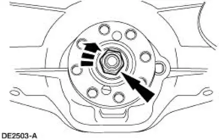
6. CAUTION: After removing the nut, discard it. Use a new nut for installation.
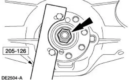
Use the special tool to hold the rear axle pinion flange while removing the nut.
7. Index-mark the rear axle pinion flange and drive pinion gear stem to maintain initial balance during installation.
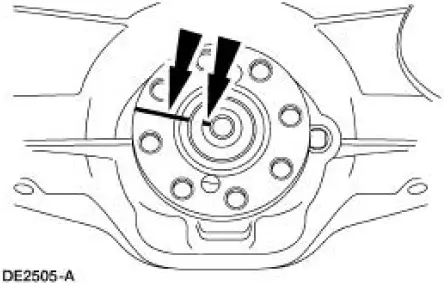
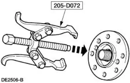
8. Using the special tool, remove the rear axle pinion flange.
 Drive Pinion Flange
Special Tool(s)
2-Jaw Puller
205-D072 (D97L-4221-A) or
equivalent
Holding Fixture, Drive Pinion
Flange
205-126 (T78P-4851-A)
Installer, Drive Pinion Flange
205-002 ...
 Installation
1. Inspect the rear axle pinion flange seal journal for rust, nicks, and
scratches prior to installing
the flange. Polish the seal journal with fine crocus cloth, if necessary.
2. Lubricate the rear ...
Other materials:
Pinpoint Tests
PINPOINT TEST A: THE SPEED CONTROL IS INOPERATIVE
Test Step
Result / Action to Take
A1 CHECK THE SPEED CONTROL SERVO VOLTAGE AND
GROUND
YesGO to A3 .
No
GO to A2 .
Key in OFF position.
Disconnect: Speed Control Servo C122.
...
Exhaust Manifold LH
Special Tool(s)
Lifting Bracket, Engine
303-D088 (D93P-6001-A2)
Support Bar, Engine
303-290-A
Removal and Installation
1. Install the special tool.
2. Install the special tools.
3. Raise and support the vehicle. For additional ...
Transmission Electronic Control System
The powertrain control module (PCM) and its input/output network
control the following transmission
operations:
Shift timing
Line pressure (shift feel)
Torque converter clutch
The transmission control is separate from the engine control s ...
