Ford Mustang (1999-2004) Service Manual: Installation
1. Install the bushings, if removed.
2. Using the transmission jack, raise the rear axle assembly into position.
3. Install the bolts and nuts.
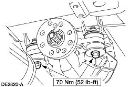
4. Install the bolts.
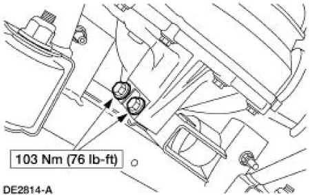
5. CAUTION: Align the index-marks.
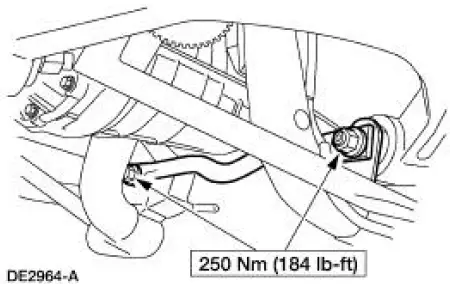
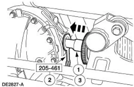
CAUTION: Install the driveshaft with new bolts. If new bolts are not available, apply Threadlock and Sealer EOAZ-19554-AA or equivalent meeting Ford specification WSKM2G351- A5 to the threads of the original bolts.
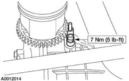
CAUTION: The driveshaft centering socket yoke fits tightly on the rear axle pinion flange pilot. To make sure that the yoke seats squarely on the flange, tighten the bolts evenly in a cross pattern as shown.
Connect the driveshaft and install the bolts.
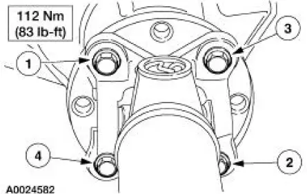
6. Install the pinion nose crossmember.
7. NOTE: The following halfshaft and knuckle assembly installation steps apply to both sides of the vehicle.
Remove the special tool.
8. CAUTION: Differential seal damage will occur if installing the halfshaft without the special tool.
Install the special tool.
9. Position the halfshaft for installation.
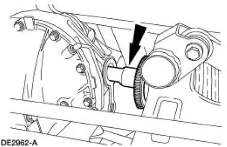
10. Seat the CV joint stub shaft in the differential side gear.
1. Slide the stub shaft into the differential housing until the shaft splines are past the differential seal.
2. Remove the special tool.
3. Align the stub shaft splines and the side gear splines, and slide the stub shaft into the gear until it seats.
- When seated, the axle circlip will lock the stub shaft in the differential side gear.
Check the circlip engagement by attempting to pull the inboard CV joint out of the differential side gear. If the circlip has not seated, push the CV joint inward until the circlip is fully engaged in the differential side gear.
11. CAUTION: Do not tighten the fastener at this time.
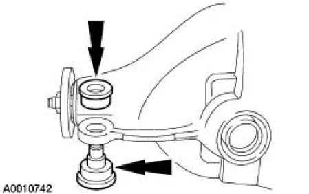
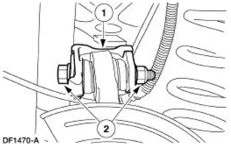
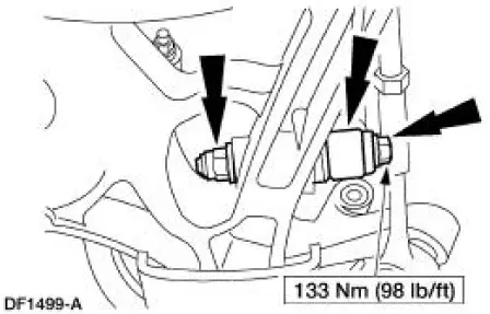
Connect the knuckle to the upper suspension arm and bushing.
1. Position the knuckle.
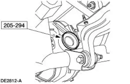
2. Install the new cam bolt and nut.
12. CAUTION: Do not tighten the fastener at this time.
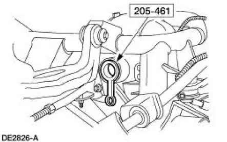
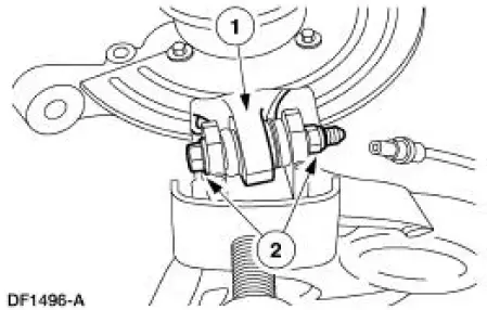
Connect the knuckle to the lower suspension arm and bushing.
1. Position the knuckle.
2. Install the new bolt and nut.
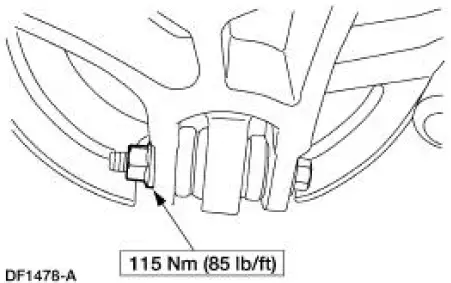
13. Connect the toe link to the knuckle.
1. Position the toe link.
2. Install the new nut.
3. Install the new cotter pin.
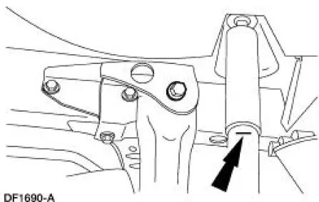
14. CAUTION: Install the hardened washer between the lower suspension arm and bushing and the shock absorber. Failure to do so can result in damage and failure of the lower suspension arm and bushing.
Position the shock absorber, and install the bolt and the new nut.
15. Install the other halfshaft and knuckle assembly, toe link, and shock absorber as described in the previous steps.
16. Raise the suspension until the shock absorbers compress to the previously established alignment mark (curb height).
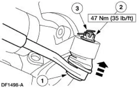
17. Tighten the nut.
18. Align the marks on the cam bolt and the upper suspension arm and bushing, and tighten the nut.
19. Repeat the two previous steps for the other knuckle.
20. Lower the suspension and remove the jack stands.
21. Apply Anti-Seize Lubricant to the rear brake anti-lock sensors where they contact the axle housing and install the anti-lock sensors.
- Use High Temperature Nickel Anti-Seize Lubricant F6AZ-9L494-AA or equivalent meeting Ford specification ESE-M12A4-A.
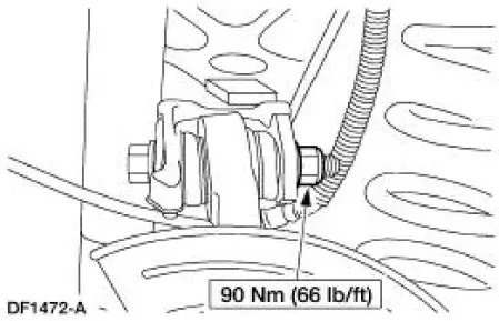
22. Install the brake disc, and the rear disc brake caliper and support bracket assembly.
23. Position the parking brake cable and conduit.
24. Connect the parking brake cable and conduit to the caliper and parking brake lever.
25. Repeat the three previous steps for the brake components on the other side of the vehicle.
26. Install the exhaust system.
27. Install the wheels and tires.
28. CAUTION: If refilling the rear axle (4001), first add 118 ml (4 oz) of Additive Friction Modifier C8AZ-19B546-A or equivalent meeting Ford specification EST-M2C118-A.
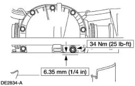
Check the lubricant level.
- If necessary, fill the rear axle housing to the level shown with SAE 75W- 140 High Performance Rear Axle Lubricant F1TZ-19580-B or equivalent meeting Ford specification WSL-M2C192-A. The refill capacity is 1.23-1.37 liters (2.6-2.9 pints).
29. Lower the vehicle.
30. Check, and adjust the wheel alignment as necessary.
 Removal
1. CAUTION: The vehicle must be on level ground and at curb height.
Mark the rear shock absorbers relative to their protective sleeve.
During installation, raise the suspension to this reference ma ...
 Axle
Axle
Special Tool(s)
2-Jaw Puller
205-D072 (D97L-4221-A) or
equivalent
Adapter for 205-S127
205-105 (T76P-4020-A3)
Bearing Preload Tool
205-395 (T93P-4220-A)
Plat ...
Other materials:
Multifunction Electronic Control Modules
Torque Specifications
Module Controlled Functions
The generic electronic module (GEM)(14B205) is the only multifunction
control module on this vehicle.
The GEM controls the following functions:
warning chimes and warning lamps
one-touch down ...
Installation
1. Make sure the anti-rattle spring is correctly positioned in the
caliper.
2. CAUTION: Make sure guide pin boots are correctly seated or damage to
guide pins
can occur.
Install the disc brake caliper.
1. Hold the guide pins stationary.
2. Inst ...
Heated Oxygen Sensor (HO2S)
Special Tool(s)
Socket, Exhaust Gas Oxygen
Sensor
303-476 (T94P-9472-A)
Material
Item
Specification
Penetrating and Lock Lubricant
or equivalent
E8AZ-19A501-
B
Removal and Installation
1. Disconnect the battery ground ...
