Ford Mustang (1999-2004) Service Manual: Removal
1. CAUTION: The vehicle must be on level ground and at curb height.
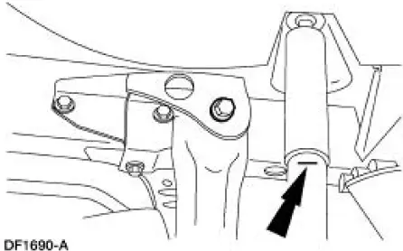
Mark the rear shock absorbers relative to their protective sleeve.
- During installation, raise the suspension to this reference mark before tightening the suspension component fasteners.
2. Raise and support the vehicle.
3. Remove the rear wheel and tire assemblies.
4. Remove the exhaust system.
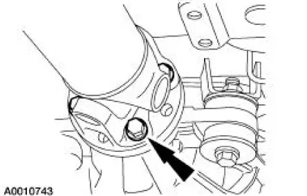
5. Remove the pinion nose crossmember.
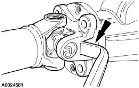
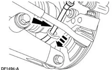
6. CAUTION: Index-mark the driveshaft flange and rear axle pinion flange (4851) to maintain initial balance during installation.
CAUTION: The driveshaft centering socket yoke fits tightly on the rear axle pinion flange pilot. Never hammer on the driveshaft (4602) or any of its components to disconnect the yoke from the flange. Pry only in the area shown, with a suitable tool, to disconnect the yoke from the flange.
Disconnect and position the driveshaft out of the way.
7. NOTE: The following halfshaft and knuckle assembly removal steps apply to both sides of the vehicle.
Disconnect the parking brake cable and conduit from the parking brake lever and the caliper.
8. Separate the parking brake cable and conduit from the knuckle.
9. Remove the rear brake disc.
- Remove the rear brake caliper and support bracket from the knuckle as an
assembly.
Wire the caliper and support bracket assembly out of the way.
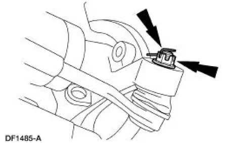
10. Remove the rear brake anti-lock sensor and position it aside.
11. Support the lower suspension arm and bushing with a jack stand.
12. Remove and discard the nut and bolt.
13. Remove and discard the cotter pin and nut.
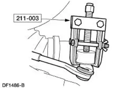
14. CAUTION: Do not strike the toe link or the knuckle to disconnect the toe link from the knuckle.
Using the special tool, disconnect the toe link from the knuckle.
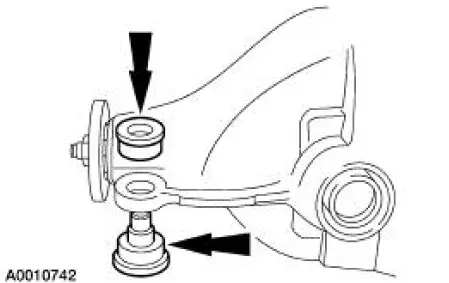
15. Mark the cam bolt position relative to the upper suspension arm and bushing.
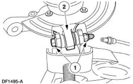
16. Disconnect the knuckle from the lower suspension arm and bushing.
1. Remove and discard the nut and bolt.
2. Disconnect the knuckle from the lower suspension arm and bushing.
17. NOTE: Mark the new cam bolt in the same position as the old one for assembly reference before discarding the old bolt.
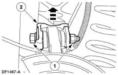
Disconnect the knuckle from upper suspension arm and bushing.
1. Remove and discard the nut and bolt.
2. Disconnect the knuckle from the upper suspension arm and bushing.
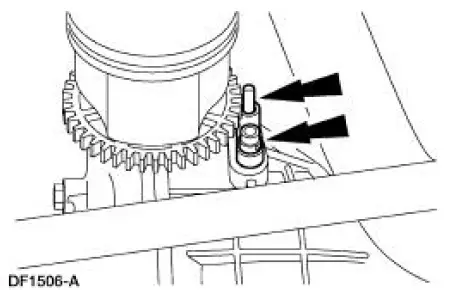
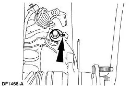
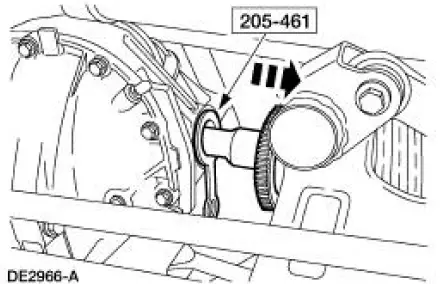
18. CAUTION: The crown on the tool forks must face away from the differential housing. Position the special tool correctly between the CV joint and the differential housing so as not to damage the differential seal.
Using the special tool, exert enough pressure to overcome the circlip and separate the CV joint from the differential side gear.
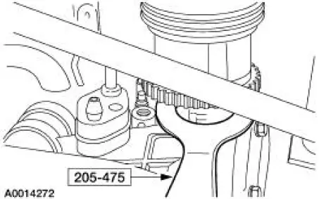
19. Install the special tool.
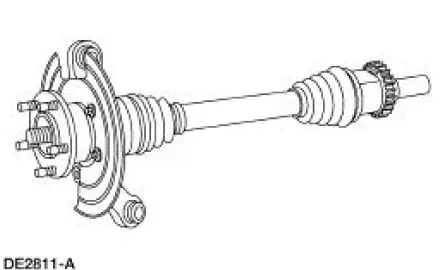
20. Remove the halfshaft and knuckle assembly from the vehicle.
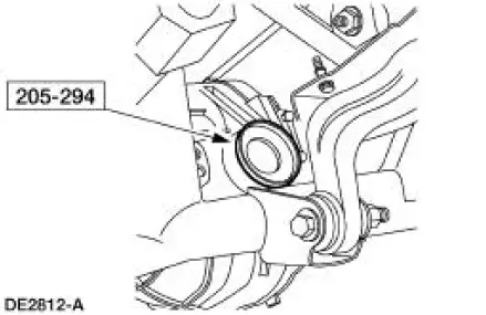
21. Insert the special tool into the housing bore.
22. Remove the other halfshaft and knuckle assembly as described in the previous steps.
23. Support the differential housing (4010) with a transmission jack.
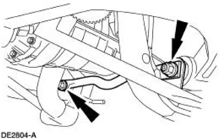
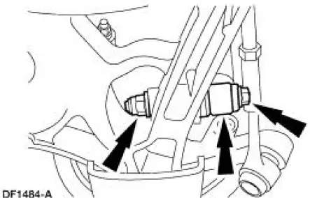
24. Remove the bolts.
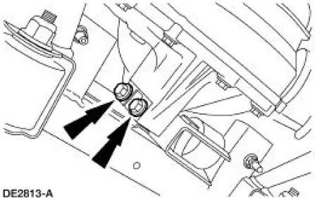
25. Remove the nuts and bolts.
26. CAUTION: Do not damage the axle vent hose. Lower the rear axle assembly from the vehicle.
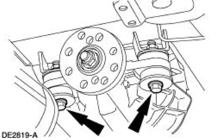
27. If removal of the mounting bushings is necessary, remove them by hand.
 Axle Housing
Special Tool(s)
Plug Set, Differential
205-294 (T89P-4850-B)
Protector, Differential Seal
(Pair)
205-461
Remover, Halfshaft
205-475
Remover, Steering Arm
2 ...
 Installation
1. Install the bushings, if removed.
2. Using the transmission jack, raise the rear axle assembly into position.
3. Install the bolts and nuts.
4. Install the bolts.
5. CAUTION: Align the index ...
Other materials:
Torque Converter Diagnosis
Prior to the installation of a new or remanufactured torque
converter, all diagnostic procedures must be
followed. This is to prevent the unnecessary installation of torque
converters. Only after a complete
diagnostic evaluation can the decision be m ...
Installation
All vehicles
CAUTION: After installing the urethane installed windshield,
the vehicle should not be
driven until the urethane adhesive has cured. The curing time at
temperatures above 13C (55
F) and relative humidity above 50% is 12-24 hours (Refer ...
Switch - Seat Regulator Control
Removal and Installation
1. Disconnect the battery. For additional information, refer to Section.
2. Remove the screws and position the seat regulator control switch aside.
3. Disconnect the electrical connector and remove the seat regulator control
swit ...
