Ford Mustang (1999-2004) Service Manual: Installation
1. NOTE: This procedure applies to both the LH and RH halfshafts.
Install a new driveshaft bearing retainer circlip.
2. Remove the special tool.
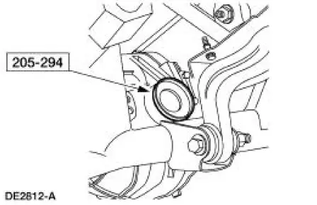
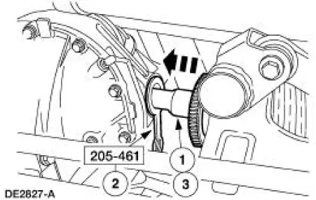
3. CAUTION: Differential seal damage will occur if installing the halfshaft without the special tool installed.
Install the special tool.
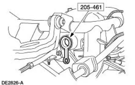
4. Position the halfshaft for installation.
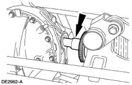
5. Seat the CV joint stub shaft in the differential side gear.
1. Slide the stub shaft into the axle housing until the shaft splines are past the differential seal.
2. Remove the special tool.
3. Align the stub shaft splines and the side gear splines, and slide the stub shaft into the gear until it seats.
- When seated, the axle circlip will lock the stub shaft in the differential side gear.
Check the circlip engagement by attempting to pull the inboard CV joint out of the differential side gear. If the circlip has not seated, push the CV joint inward until the circlip is fully engaged in the differential side gear.
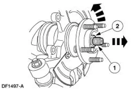
6. Connect the axle shaft to the hub.
1. Making sure the serrations on the shaft line up with the serrations in the hub, install the axle shaft into the hub.
2. Install a new retainer. Do not tighten the retainer at this time.
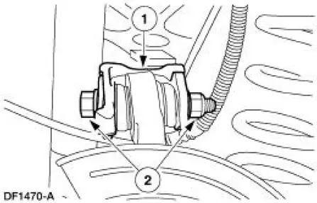
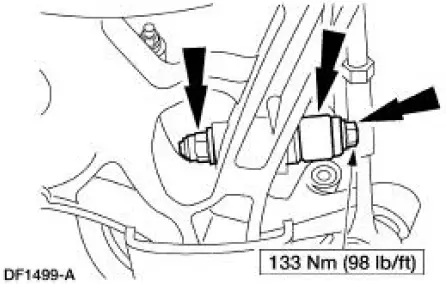
7. Connect the suspension upper arm and bushing to the knuckle.
1. Position the suspension upper arm and bushing on the knuckle.
2. Install the new bolt and a new nut. Do not tighten the nut at this time.
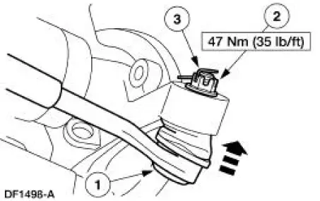
8. Connect the tie-rod end to the knuckle.
1. Position the tie-rod link in the knuckle.
2. Install a new nut.
3. Install a new cotter pin.
9. Raise the suspension until the shock absorber is compressed to the previously established alignment mark (curb height).
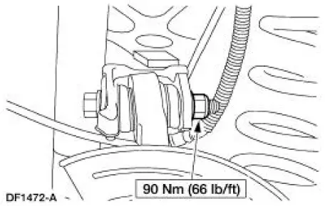
10. Connect the shock absorber to the suspension lower arm and bushing and install the new bolt and a new nut.
11. Tighten the nut.
12. Lower the suspension and remove the jack stand.
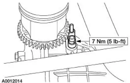
13. Apply Anti-Seize Lubricant to the rear brake anti-lock sensor where it contacts the axle housing and install the anti-lock sensor.
- Use High Temperature Nickel Anti-Seize Lubricant F6AZ-9L494-AA or equivalent meeting Ford specification ESE-M124A-A.
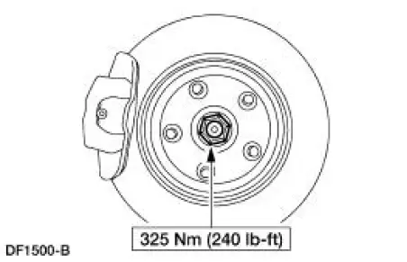
14. Install the rear brake disc.
15. Tighten the retainer.
16. Install the wheel and tire assembly.
17. Lower the vehicle.
18. Check the wheel alignment. Adjust as necessary.
 Removal
NOTE: This procedure applies to both the LH and RH halfshafts.
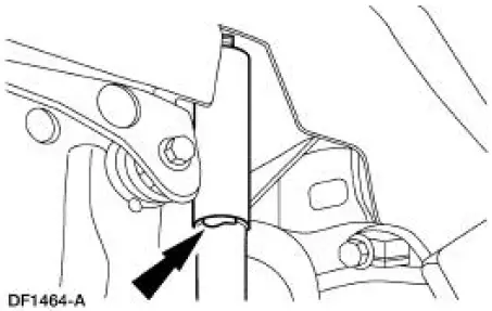
1. CAUTION: The vehicle must be on level ground and at curb height.
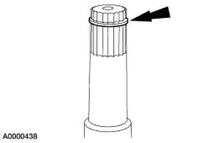
Mark the rear shock absorber relative to the protective sleeve.
...
 Halfshaft Joint
Special Tool(s)
Driver
205-199 (T83T-3132-A1)
Hub Bearing Cup Replacer
205-147 (T80T-4000-P)
Sensing Ring Replacer
206-041 (T89P-20202-A)
Disassembly
1. CAUTION: Do ...
Other materials:
Exhaust System (Description and Operation)
WARNING: The normal operating temperature of the exhaust system is very
high. Never
attempt to repair any part of the system until it has cooled. Be especially
careful when working
around the three way catalytic converter. The temperature of the three way
c ...
Principles of Operation
Power Window Control
NOTE: Battery power and ground must be removed before disconnecting the
GEM connectors to
avoid setting false DTCs.
The driver power window one-touch down operation is controlled by the
generic electronic module
(GEM). This featur ...
Purging - CII Power Steering Pump
Special Tool(s)
Vacuum Pump
416-D002 (D95L-7559-A) or
Equivalent
CAUTION: If the air is not purged from the power steering system
correctly, premature
power steering pump failure can result. This condition can occur on pre-delivery
vehicles ...
