Ford Mustang (1999-2004) Service Manual: Removal
NOTE: This procedure applies to both the LH and RH halfshafts.
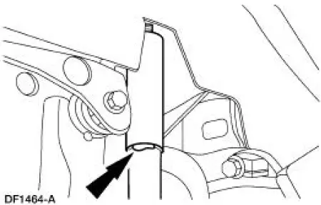
1. CAUTION: The vehicle must be on level ground and at curb height.
Mark the rear shock absorber relative to the protective sleeve.
- During installation, raise the suspension to this reference mark before tightening the suspension component fasteners.
2. Raise and support the vehicle.
3. Remove the rear wheel and tire assembly.
4. Remove and discard the rear axle wheel hub retainer.
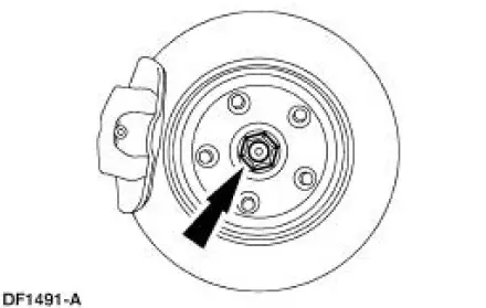
5. Remove the rear brake disc.
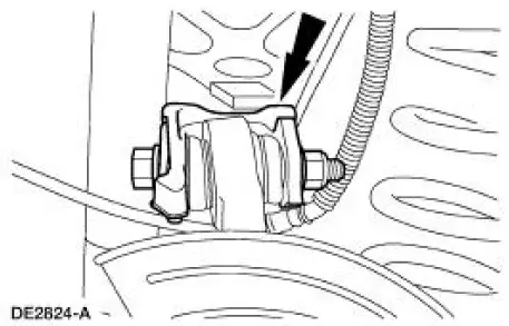
6. Remove the rear brake anti-lock sensor and position aside.
7. Support the suspension lower arm and bushing. This will ease removal of the lower shock absorber mount bolt.
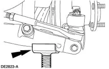
8. Disconnect the shock absorber at the suspension lower arm and bushing. Discard the nut and the bolt.
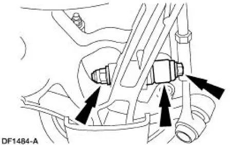
9. Remove and discard the cotter pin and the nut.
10. Using the special tool, disconnect the tie-rod link at the knuckle.
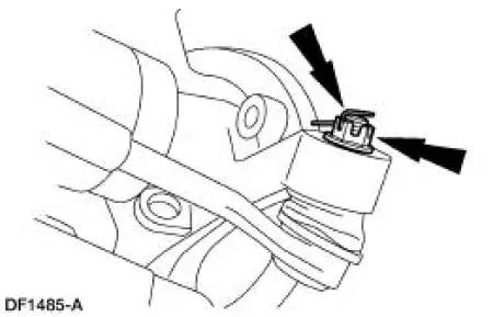
11. Disconnect the suspension upper arm and bushing at the knuckle. Discard the nut and the bolt.
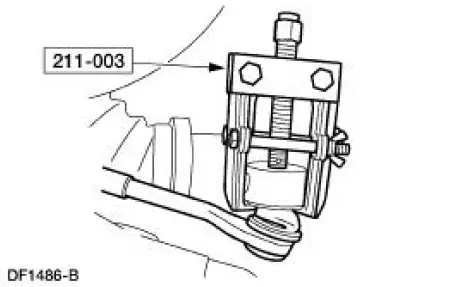
12. Using the special tool, press the outboard CV joint until it is loose in the hub.
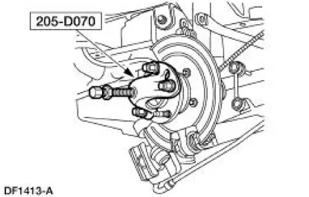
13. CAUTION: Do not over-angulate the outboard CV joint or damage the boot.
While lowering the knuckle, remove the CV joint from the hub.
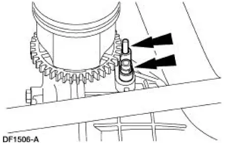
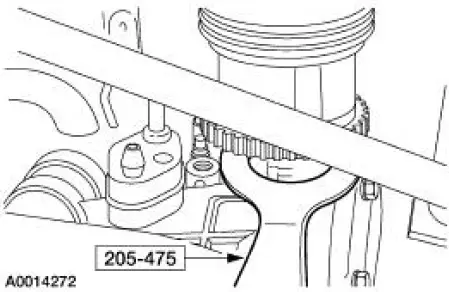
14. CAUTION: The crown on the tool forks must face away from the axle housing.
Position the special tool correctly between the CV joint and the axle housing so as not to damage the differential seal.
Using the special tool, exert enough pressure to overcome the circlip and separate the CV joint (4K326) from the differential side gear.
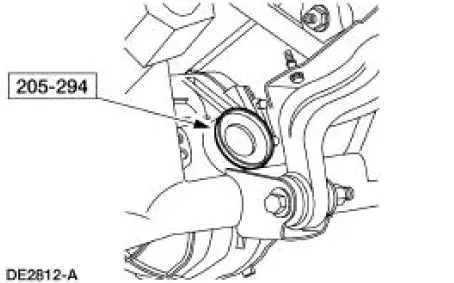
15. CAUTION: Do not damage the differential seal.
Carefully remove the halfshaft (4K138) with both hands.
16. Install the special tool.
 Halfshaft
Special Tool(s)
Differential Plug
205-294 (T89P-4850-B)
Differential Seal Protector
205-461
Front Hub Remover
205-D070 (D93P-1175-B) or
Equivalent
Halfshaft ...
 Installation
1. NOTE: This procedure applies to both the LH and RH halfshafts.
Install a new driveshaft bearing retainer circlip.
2. Remove the special tool.
3. CAUTION: Differential seal damage will occur if i ...
Other materials:
Air Conditioning Line (Peanut) Fitting
Disconnect
1. CAUTION: Support the female fitting with a wrench to prevent the
tubes from
twisting.
Remove the nut from the peanut fitting.
2. Pull the peanut fitting apart.
3. CAUTION: Do not use metal tools to remove the O-ring seal. They can
cause axi ...
Manual Transmission
The T5OD 5-speed transmission:
fifth speed gear functions as an overdrive gear.
forward gears are synchronized and helical cut.
shift interlock system prevents the engagement of more than one
gear.
Transmission, Manual Five-Speed
T ...
Piston - Pin Connecting Rod, Floating Pin
Material
Item
Specification
SAE 5W-20 Premium Synthetic
Blend Engine Oil
XO-5W20-QSP
WSS-M2C153-
H
Disassembly
1. Remove the clips.
2. Remove the piston pin from the piston and connecting rod assembly.
3. Remove the connecting rod ...
