Ford Mustang (1999-2004) Service Manual: Installation
1. CAUTION: Timing chain procedures must be followed exactly or damage to the pistons or valves will result.
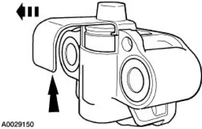
Compress the tensioner plunger, using a soft-jawed vise.
2. Install a retaining clip on the tensioner to hold the plunger in during installation.
- Remove the tensioner from the vise.
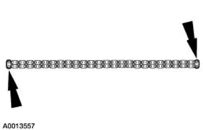
3. If the copper links are not visible, mark one link on one end and one link on the other end, and use as timing marks.
4. Install the timing chain guides.
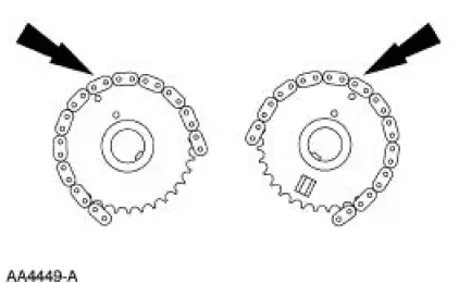
5. Rotate the LH camshaft sprocket until the timing mark is approximately at the 12 o' clock position. Rotate the RH camshaft timing sprocket until the timing mark is approximately in the 11 o' clock position.

6. CAUTION: Unless otherwise instructed, at no time when the timing chains are removed and the cylinder heads are installed is the crankshaft or the camshaft to be rotated. Severe piston and valve damage will occur.
CAUTION: Rotate the crankshaft counterclockwise only. Do not rotate past position shown or severe piston or valve damage will occur.
Using the special tool, position the crankshaft.
7. Remove the special tool.
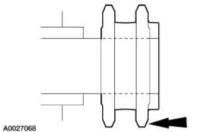
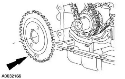
8. Install the crankshaft sprocket with the flange facing forward.
9. NOTE: LH timing chain shown; RH similar.
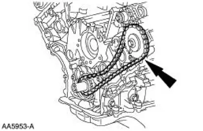
Install the LH timing chain onto the crankshaft sprocket, aligning the one copper link on the timing chain with the slot on the crankshaft sprocket.
10. Verify the camshaft sprocket to copper link alignment.
11. NOTE: LH shown; RH similar.
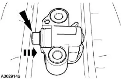
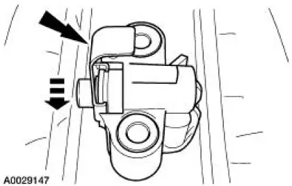
Position the tensioner arms and tensioners, and install the bolts.
12. Remove the retaining clips from the timing chain tensioners.
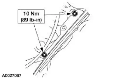
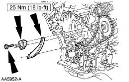
13. Position the crankshaft sensor ring on the crankshaft.
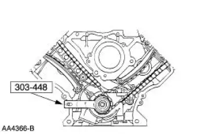
14. Install the engine front cover. For additional information, refer to Engine Front Cover in this section.
 Removal
CAUTION: Since the engine is not free-wheeling, if the crankshaft or
the camshafts are
moved in any manner during removal and installation, the crankshaft and the
camshafts must
be re-synchronized.
...
 Valve - Springs, Retainer and Valve Stem Seal
Special Tool(s)
Compressor, Valve Spring
303-452 (T93P-6565-AR)
Installer, Valve Stem Oil Seal
303-383 (T91P-6571-A)
Compressor, Valve Spring
303-567 (T97P- ...
Other materials:
Pinpoint Tests
PINPOINT TEST A: THE BRAKES PULL OR DRIFT
Test Step
Result / Action to Take
A1 CHECK THE TIRES
YesGO to A2 .
No
CORRECT as necessary.
RETEST for normal
operation.
NOTE: Check tire pressure with the brakes off.
Check tires for u ...
Engine (Installation)
Special Tool(s)
Heavy Duty Floor Crane
014-00071 or equivalent
Spreader Bar
303-D089 (D93P-6001-A3) or
equivalent
Material
Item
Specification
SAE 5W-20 Premium Synthetic
Blend Motor Oil
XO-5W20-QSP or equivalent ...
Glass, Frames and Mechanisms
WINDOW REGULATOR ELECTRIC DRIVE
CURRENT DRAW
General Specifications
Torque Specifications
...
