Ford Mustang (1999-2004) Service Manual: Installation
1. NOTE: The LH side is shown, and the RH is similar.
Install the supply manifold and tighten the four bolts.
2. Connect the EGR vacuum line.
3. Install the EGR to exhaust manifold tube. For additional information, refer to Section.
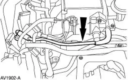
4. NOTE: The engine is removed for clarity.
Position the EVR bracket and tighten the bolts.
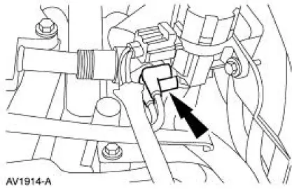
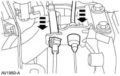
5. Connect the EVR solenoid vacuum lines.
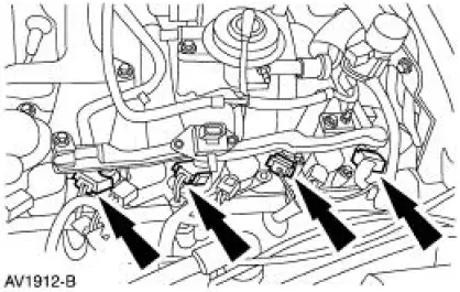
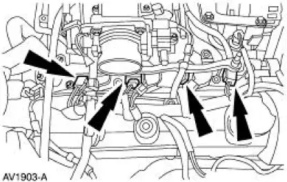
6. Connect the LH fuel injector electrical connectors.
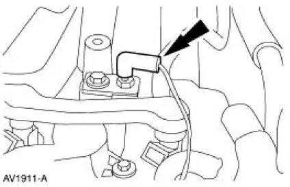
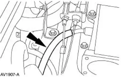
7. Connect the ground wire.
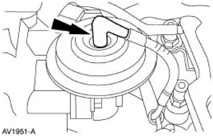
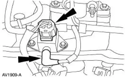
8. Connect the fuel pressure sensor electrical connector and the vacuum hose.
9. NOTE: Make sure the locking clips are fully engaged into the bracket.
Reposition the accelerator cable and the speed control cable (if equipped) and install the cables into the bracket.
10. Connect the hose.
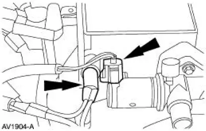
11. Connect the IAC electrical connector and install the main chassis vacuum hose.
12. Connect the four RH fuel injector electrical connectors.
13. Connect the PCV hose.
14. Position the IAC hose and connect the hose.
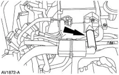
15. Install the throttle body.
16. Connect the fuel line.
17. Connect the air cleaner outlet tube.
18. Connect the battery ground cable.
 Removal
WARNING: Do not smoke or carry lighted tobacco or open flame of any
type when
working on or near any fuel related components. Highly flammable mixtures are
always present
and may be ignited. Failure ...
 Fuel Charging and Controls - Cobra 4.6L (4V)
General Specifications
Torque Specifications
...
Other materials:
Brake Caliper Anchor Plate
Removal
1. Remove the pads. For additional information, refer to Pads in this
section.
2. Remove the anchor plate (2B292).
1. Remove and discard the anchor plate bolts.
2. Remove the anchor plate.
Installation
1. CAUTION: Use correct t ...
Instrument Cluster (Diagnosis and Testing)
Refer to Wiring Diagrams Cell 60 , Instrument Cluster for schematic and
connector information.
Special Tool(s)
Worldwide Diagnostic System
(WDS)
418-F224,
New Generation STAR (NGS)
Tester
418-F052, or equivalent
diagnostic tool
...
Rear Drive Axle/Differential - Ford 7.5-Inch Ring Gear
General Specifications
a: In-vehicle repair refill capacities are determined by filling the rear axle
with the specified lubricant to
6.4-14.3-mm (1/4-9/16-in) below the bottom of the fill hole.
Torque Specifications
...
