Ford Mustang (1999-2004) Service Manual: Installation
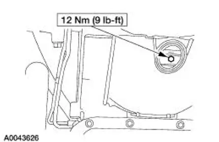
1. NOTE: A new torque converter drain plug must be used.
Install the torque converter drain plug.
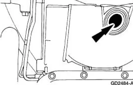
2. Install the torque converter housing plug.
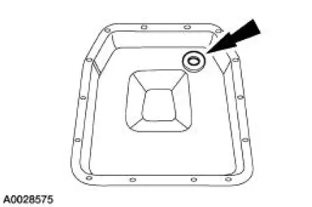
3. CAUTION: If installing a new filter, and the seal remains in the main control bore, carefully use a small screwdriver to remove the seal. Use care not to damage the main control bore.
NOTE: If transmission is being repaired for a contamination-related failure, use a new filter and seal. The filter may be reused if no excessive contamination is present.
Install a new fluid filter and seal as required.
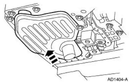
4. Position the pan magnet into the transmission fluid pan.
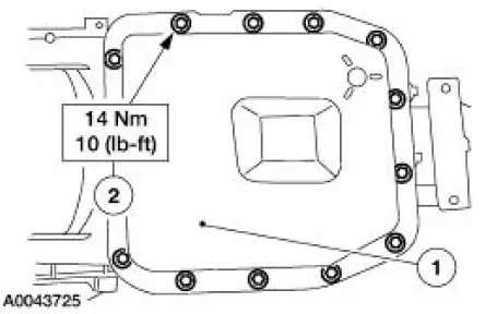
5. NOTE: The transmission fluid pan gasket is reusable. Clean and inspect for damage; if not damaged, the gasket should be reused.
Install the transmission fluid pan and gasket.
1. Position the transmission fluid pan and gasket.
2. Install the transmission fluid pan bolts.
6. Lower the vehicle.
7. NOTE: When the battery is disconnected and reconnected, some abnormal drive symptoms may occur while the vehicle relearns its adaptive strategy. The vehicle may need to be driven 16 km (10 miles) or more to relearn the strategy.
Connect the battery ground cable. For additional information, refer to Section.
8. NOTE: When filling a dry transmission and converter, start with a minimum of 4.7 liters (5 quarts).
Fill the transmission to the correct level with clean automatic transmission fluid.
 Removal
1. Disconnect the battery ground cable. For additional information, refer
to Section.
2. Raise and support the vehicle. For additional information, refer to
Section.
3. Place a drain pan under ...
 Transmission Filler Tube
Removal
1. Remove the bolt.
2. Remove the fluid filler tube.
Installation
1. To install, reverse the removal procedure.
...
Other materials:
Removal
1. Remove the differential assembly from the differential housing. For
additional information, refer
to Differential Case in this section.
2. CAUTION: Record the torque necessary to maintain rotation of the drive
pinion gear
through several revolutions prio ...
A/C Compressor and Clutch Assembly
NOTE: Internal A/C compressor components are not serviced separately.
The FS-10 A/C compressor
is serviced only as an assembly. The A/C clutch pulley, A/C clutch field coil
(19D798) and the shaft
seal are serviceable.
The FS-10 A/C compressor has the follo ...
Exterior Lighting
Torque Specifications
Exterior Lighting
The exterior lighting system consists of the following components:
headlamps (13008)
parking lamps
rear lamps (13404)
high mounted stoplamp
license lamps
front turn lamps
reversing lamps
fog ...
