Ford Mustang (1999-2004) Service Manual: Pinpoint Test A: The Air Bag Warning Indicator Is Illuminated Continuously - RCM Disconnected, Inoperative or Lost/Low Ignition Feed
Normal Operation
NOTE: During normal operation the air bag indicator will be lit continuously for 6 seconds after the ignition switch is placed in the RUN position and after five cycles of a lamp fault code (LFC) if a fault exists. Be sure to cycle the ignition switch and look for a 6 second indicator prove-out without LFCs.
The restraints control module (RCM) will communicate diagnostic trouble codes (DTCs) to the scan tool through the data link connector (DLC). If the scan tool displays NO COMMUNICATION when retrieving continuous DTCs, Go To Pinpoint Test P to troubleshoot the system.
Possible Causes
An air bag indicator that is illuminated continuously can be caused by one of the following:
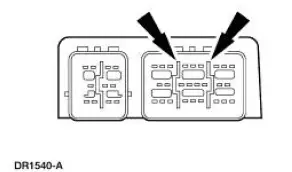
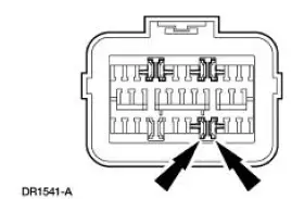
- worn or damaged shorting bar or camming beam.
- the ignition circuit damaged.
- the RCM disconnected from the vehicle harness.
- a loss of RCM ground circuits.
- the RCM inoperative.
- circuitry.
PINPOINT TEST A: THE AIR BAG WARNING INDICATOR IS ILLUMINATED CONTINUOUSLY - RCM DISCONNECTED, INOPERATIVE, OR LOST/LOW IGNITION FEED
| Test Step | Result / Action to Take |
| A1 CHECK FOR CONTINUOUS OR ON-DEMAND SELF TEST DTCs | Yes If continuous DTCs were retrieved, GO to A3 . If on-demand DTCs were retrieved, GO to the Restraints Control Module (RCM) Diagnostic Trouble Code (DTC) Priority Table in this section for pinpoint test direction. No GO to A2 . |
|
|
| A2 CHECK THE RCM CONNECTION | Yes GO to A3 . No CONNECT C2041 and engage the locking tabs. GO to A7 . |
| WARNING: If the supplemental restraint system
(SRS) is
being serviced, the system must be deactivated and restraint
system diagnostic tools must be installed. Refer to Air Bag
Supplemental Restraint System (SRS) in this section. The air bag restraint system diagnostic tools must be removed and the air bag modules reconnected when the system is reactivated to avoid non-deployment in a collision, resulting in possible personal injury. NOTE: Diagnostics or repairs are not to be performed on a seat equipped with a seat side air bag with the seat in the vehicle. Prior to attempting to diagnose or repair a seat concern when equipped with a seat side air bag, the seat must be removed from the vehicle and the restraint system diagnostic tools must be installed in the seat side air bag electrical connectors. The restraint system diagnostic tools must be removed prior to operating the vehicle over the road. NOTE: After diagnosing or repairing an SRS, the restraint system diagnostic tools must be removed before operating the vehicle over the road. NOTE: After diagnosing or repairing a seat system, the restraint system diagnostic tools must be removed before operating the vehicle over the road. NOTE: The SRS must be fully operational and free of faults before releasing the vehicle to the customer.
|
|
| A3 CHECK THE RCM CONNECTOR | Yes CORRECT connector concerns. GO to A7 . No GO to A4 . |
|
|
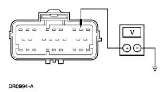
| A4 CHECK THE IGNITION CIRCUIT 611 (WH/OG) FOR AN OPEN | Yes GO to A5 . No REPAIR the circuit. GO to A7 . |
|
|
| A5 CHECK THE GROUND CIRCUIT 397 (BK/WH) FOR AN OPEN | Yes GO to A6 . No REPAIR the circuit. GO to A7 |
|
|
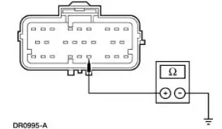
| A6 CHECK CIRCUIT 608 (BK/YE) FOR A SHORT TO GROUND | Yes REPAIR the circuit. GO to A7 . No INSTALL a new RCM. GO to A7 . |
|
|
| A7 CHECK FOR ADDITIONAL DTCs | Yes Do not clear any DTCs until all DTCs have been resolved. GO to the Restraints Control Module (RCM) Diagnostic Trouble Code (DTC) Priority Table in this section for pinpoint test direction. No RECONNECT the system. REACTIVATE the system. PROVE OUT the system. REFER to Air Bag Supplemental Restraint System (SRS) in this section. CLEAR all DTCs. |
|
 Pinpoint Tests - Air Bag Supplemental Restraint System
(SRS)
Pinpoint Tests - Air Bag Supplemental Restraint System
(SRS)
Special Tool(s)
73III Automotive Meter
105-R0057 or equivalent
Diagnostic Tool, Restraint
System
418-F088 (105-R0012)
Worldwide Diagnostic System
(WDS)
418 ...
 Pinpoint Test B: LFC 21/DTC B1921 - RCM Bracket Ground Resistance High
Normal Operation
WARNING: The tightening torque of the restraints control module
(RCM) retaining bolts is
critical for proper air bag supplemental restraint system (SRS)
operation. Refer to ...
Other materials:
Changing a bulb
Lamp Assembly Condensation
Exterior lamps are vented to accommodate normal changes in pressure.
Condensation can be a natural by-product of this design. When moist air
enters the lamp assembly through the vents, there is a possibility that
condensation can oc ...
Manual Transaxle/Transmission - TR3650
General Specifications
Torque Specifications
...
Switch - Deactivator
Removal
1. Disconnect the battery ground cable.
2. Remove the deactivator switch.
1. Disconnect the deactivator switch electrical connector.
2. Detach the lower deactivator switch hook.
3. Detach the upper deactivator pivot.
Installation
1. N ...
