Ford Mustang (1999-2004) Service Manual: Pinpoint Test F: LFC 16/DTC B1888 - Passenger Air Bag Circuit Shorted to Ground
Normal Operation
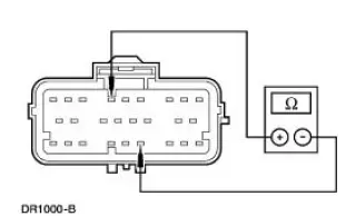
The restraints control module (RCM) checks for passenger air bag circuit shorts to ground by monitoring the voltage of circuits 607 (LB/OG) and 616 (PK/BK) at pins 6 and 7. If the RCM detects a short to ground on either of these pins, it will store a diagnostic trouble code (DTC) B1888 in memory and flash a lamp fault code (LFC) 16 (or higher priority code if one exists) on the air bag indicator.
Possible Causes
A passenger air bag circuit short to ground can be caused by:
- a short to ground on circuit 607 (LB/OG).
- a short to ground on circuit 616 (PK/BK).
- a short to ground on the passenger air bag module.
- an RCM internal concern.
PINPOINT TEST F: LFC 16/DTC B1888 - PASSENGER AIR BAG CIRCUIT SHORTED TO GROUND
| Test Step | Result / Action to Take |
| F1 CHECK FOR A HARD OR INTERMITTENT DTC | Yes This is a hard fault. The fault condition is still present. This fault cannot be cleared until it is corrected and the DTC is no longer retrieved during the on-demand self test. GO to F2 . No This is an intermittent fault. The fault condition is not present at this time. GO to F5 . |
|
|
| F2 CHECK THE PASSENGER AIR BAG MODULE | Yes GO to F3 . No INSTALL a new passenger air bag module. GO to F6 . |
| WARNING: If the supplemental restraint system
(SRS) is
being serviced, the system must be deactivated and restraint
system diagnostic tools must be installed. Refer to Air Bag
Supplemental Restraint System (SRS) in this section. The air bag restraint system diagnostic tools must be removed and the air bag modules reconnected when the system is reactivated to avoid non-deployment in a collision, resulting in possible personal injury. NOTE: Diagnostics or repairs are not to be performed on a seat equipped with a seat side air bag with the seat in the vehicle. Prior to attempting to diagnose or repair a seat concern when equipped with a seat side air bag, the seat must be removed from the vehicle and the restraint system diagnostic tools must be installed in the seat side air bag electrical connectors. The restraint system diagnostic tools must be removed prior to operating the vehicle over the road. NOTE: After diagnosing or repairing an SRS, the restraint system diagnostic tools must be removed before operating the vehicle over the road. NOTE: After diagnosing or repairing a seat system, the restraint system diagnostic tools must be removed before operating the vehicle over the road. NOTE: The SRS must be fully operational and free of faults before releasing the vehicle to the customer.
|
|
| F3 CHECK THE PASSENGER AIR BAG MODULE CIRCUIT | Yes GO to F4 . No INSTALL a new RCM. GO to F6 |
|
|
| F4 CHECK THE PASSENGER AIR BAG MODULE WIRING | Yes REPAIR as necessary. GO to F6 . No GO to F6 |
|
|
| F5 CHECK FOR AN INTERMITTENT FAULT | Yes CHECK for causes of intermittent short to ground on circuit 607 (LB/OG) and circuit 616 (PK/BK). Attempt to recreate the hard fault by flexing the wire harness and cycling the ignition key frequently. REPAIR any intermittent concerns found. GO to F6 . No GO to F6 . |
|
|
| F6 CHECK FOR ADDITIONAL DTCs | Yes Do not clear any DTCs until all DTCs have been resolved. GO to the Restraints Control Module (RCM) Diagnostic Trouble Code (DTC) Priority Table in this section for pinpoint test direction. No RECONNECT the system. REACTIVATE the system. PROVE OUT the system. REFER to Air Bag Supplemental Restraint System (SRS) in this section. CLEAR all DTCs. |
|
 Pinpoint Test E: LFC 15/DTC B1916 - Driver Air Bag Circuit Shorted to
Battery or Ignition
Pinpoint Test E: LFC 15/DTC B1916 - Driver Air Bag Circuit Shorted to
Battery or Ignition
Normal Operation
The restraints control module (RCM) checks for driver air bag circuit
shorts to battery or ignition by
monitoring the voltage of circuit 614 (GY/OG) and 615 (GY/WH) at pins 3 and ...
 Pinpoint Test G: LFC 16/DTC B1925 - Passenger Air Bag Circuit Shorted to
Battery or Ignition
Pinpoint Test G: LFC 16/DTC B1925 - Passenger Air Bag Circuit Shorted to
Battery or Ignition
Normal Operation
The restraints control module (RCM) checks for passenger air bag circuit
shorts to battery or ignition
by monitoring the voltage of circuits 607 (LB/OG) and 616 (PK/BK) at pins 6 ...
Other materials:
Installation
LH mount
1. Position the engine mount and install the bolt and studbolts.
2. Attach the ground cables and install the nuts.
RH mount
3. Position the engine mount and install the bolts and studbolt.
4. Attach the wiring harness and install the nut.
Both ...
Transmission Control Switch
Removal
1. Remove the shifter top control panel.
2. Disconnect the electrical connectors.
3. Remove the shifter bezel.
4. Remove the bulb from the bezel.
5. Disconnect the TCS connector.
6. CAUTION: Extra force may be needed to lift up on the handl ...
Pinpoint Test A: The Air Bag Warning Indicator Is Illuminated Continuously
- RCM
Disconnected, Inoperative or Lost/Low Ignition Feed
Normal Operation
NOTE: During normal operation the air bag indicator will be lit continuously
for 6 seconds after the
ignition switch is placed in the RUN position and after five cycles of a lamp
fault code (LFC) if a fault
exists. Be sure to cycle the ignit ...
